


Views: 0 Author: Site Editor Publish Time: 2026-08-28 Origin: Site


Tightening energy compliance standards and rising operational costs continually push modern facilities away from traditional AC systems. In commercial HVAC and data center applications, achieving high efficiency is no longer optional. Upgrading legacy infrastructure demands smarter, leaner solutions to stay competitive.
Transitioning from AC to Electronically Commutated (EC) technology requires much more than a simple component swap. It represents a complete system-level upgrade. This fundamental shift completely alters existing control logic. It also redefines spatial design parameters inside critical equipment rooms.
This comprehensive guide evaluates the technical viability and mechanical realities of executing an AC fan replacement EC fan project. You will discover how to navigate the strict commercial justification properly. You will assess alternative configurations and implement modular array designs seamlessly. Expect highly actionable insights on overcoming common retrofitting risks. We will help you maximize system reliability and future-proof your facility against strict energy regulations.
Traditional AC induction motors suffer from inherent structural inefficiencies. They rely on inducing a magnetic field across an air gap. The rotor must always spin slightly slower than the stator field. Engineers call this phenomenon "slip." Slip generates significant excess heat inside the motor housing. It wastes valuable electrical power entirely. When you throttle an AC motor below its peak RPM, its efficiency plummets drastically. Traditional systems often use mechanical dampers to reduce airflow. This strategy is highly wasteful. It is like driving a car while forcefully pressing the brake pedal.
Modern HVAC systems rarely operate at 100% capacity continuously. The real magic happens during partial-load conditions. Here, we see a fundamental difference in performance curves. EC technology shines when airflow demands drop. These modern units maintain up to 90% efficiency across a surprisingly wide operational range. Conversely, AC setups drop off sharply outside their optimal speed window. Slowing down an EC unit reduces power consumption exponentially according to the affinity laws. A mere 20% reduction in speed yields nearly a 50% drop in energy usage.
Table: Performance Comparison Across Motor Technologies
| Feature | Legacy AC Motor | EC Motor Technology |
|---|---|---|
| Peak Efficiency | 60% - 75% | Up to 90% |
| Partial-Load Efficiency | Drops significantly | Remains consistently high |
| Heat Generation | High (requires more cooling) | Very low (improves facility cooling) |
| Speed Control | External components needed | Fully integrated natively |
Legacy air handling units typically rely on complex belt-and-pulley mechanisms. These mechanical systems create endless headaches for facility managers. Belts stretch over time. They require frequent manual tensioning. As they wear down, they release fine rubber dust into the clean airstream. This particulate matter fouls expensive filters prematurely. Upgrading to direct-drive units removes these mechanical failure points entirely. You eliminate ongoing mechanical upkeep. Bearings last longer. You never have to purchase or replace another worn drive belt.
Measurable success defines any strong business case. Your primary ROI metric involves direct kilowatt-hour reductions at the meter. However, secondary savings are equally important. Because EC motors run significantly cooler, your facility spends less energy removing rejected motor heat. This lowers overall cooling demands. Labor savings also pile up quickly. Maintenance teams spend zero hours adjusting pulleys or greasing external pillow block bearings.
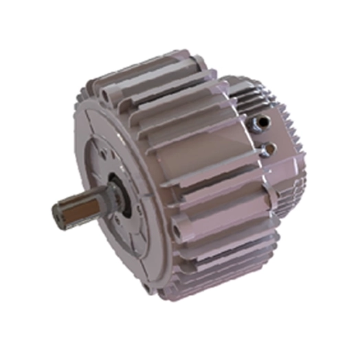
Many designers attempt a halfway solution. They attach an external Variable Frequency Drive (VFD) to a standard AC motor. This approach requires separate mounting hardware. It demands complex shielded wiring between components. Technicians must perform meticulous software tuning to optimize the drive parameters. In contrast, an EC Motor With Inverter arrives as a factory-matched package. Engineers design the motor, the internal electronics, and the impeller to work together flawlessly. It acts as a perfectly optimized, plug-and-play solution right out of the box.
AC setups paired alongside external VFDs generate notorious secondary problems. They produce choppy electrical waveforms. This creates a loud, whining motor hum inside the ductwork. The noise travels quickly into occupied office spaces. These external drives also generate electromagnetic interference (EMI). EMI easily disrupts sensitive facility sensors nearby. Furthermore, VFDs induce stray voltages along the motor shaft. These stray currents eventually discharge across the internal bearings. We call this destructive process bearing fluting.
Modern integrated systems solve these exact issues natively. Their internal commutation circuitry smooths out electrical harmonics actively. You experience exceptionally quiet operation. You protect your mechanical infrastructure from invisible electrical damage automatically.
Physical constraints dictate many retrofit decisions. Traditional AC induction motors are extremely bulky. Adding an external drive box to the cabinet wall consumes even more valuable enclosure space. This cramped environment makes future maintenance difficult. External-rotor EC motors offer a highly compact, flat profile. The motor itself sits entirely inside the fan impeller hub. This ingenious design saves critical space inside air handling units. It also reduces the overall physical weight imposed on structural supports.
Upgrading rarely involves a simple one-to-one swap. We typically replace one massive, heavy AC blower with a "wall" of smaller units. Industry professionals call this a modular fan array. This strategy introduces massive redundancy benefits to your facility. We refer to this as N+1 reliability. If one single fan fails unexpectedly, the remaining fans automatically ramp up their speed. They maintain the required system airflow seamlessly. You never experience a complete loss of cooling.
Logistically, building an array is much easier. Removing a thousand-pound legacy blower usually requires cranes or demolition torches. Conversely, smaller modular fans easily fit through standard commercial doorways. Technicians can load them onto standard passenger elevators. You completely avoid expensive heavy rigging contracts.
You must move past rudimentary on/off contactors. Modern setups demand precise digital control algorithms. These advanced fans natively support all standard industry communication protocols. You can command them using simple 0-10V analog signals. You can use Pulse Width Modulation (PWM). They also speak complex digital languages perfectly. Most units interface beautifully using Modbus RTU or BACnet protocols. This allows deep, transparent integration into your existing Building Management System (BMS).
Watch out for specific physical hurdles during installation. You cannot simply bolt new fans into an empty box. You must construct custom blank-off plates. These metal bulkheads prevent unwanted air bypass around the new fan frames. Structural modifications to the Air Handling Unit (AHU) might be necessary to support the new array wall safely.
Electrical transitions also require careful planning. Legacy infrastructure often provides raw 3-phase AC power directly to a motor starter. New electronic systems require specific input fusing and dedicated grounding. You must manage this electrical transition precisely to protect the sensitive internal inverters.
Never guess your current performance metrics. Always measure existing power consumption precisely in kilowatts (kW). Record the actual delivered airflow in cubic feet per minute (CFM). You must check the system static pressure thoroughly before finalizing any new specification. Accurate baselines allow you to prove your eventual energy savings later. Use calibrated instruments to gather this preliminary data.
Map out the higher upfront cost of your equipment precisely. Compare this initial capital expenditure against localized utility rebates. Many power companies offer lucrative incentives for eliminating outdated belt-driven equipment. Next, factor in the ongoing operational savings. Calculate the projected drop in monthly energy bills. Include the reduction in routine maintenance labor. This clear mathematical model easily justifies the upgrade to facility stakeholders.
Evaluate your unique facility needs carefully. Modern data centers track strict Power Usage Effectiveness (PUE) metrics closely. Critical healthcare facilities demand absolute, uninterrupted uptime. Assess whether your specific application requires the failover capabilities provided by modular arrays. If a brief outage causes massive financial loss, you absolutely need N+1 redundancy.
Do not rush into a full facility rollout immediately. We strongly recommend initiating a limited pilot retrofit first. Select a single, representative Air Handling Unit (AHU) or Computer Room Air Conditioning (CRAC) unit. Perform the complete upgrade on this single test subject. Monitor its performance for several weeks. Validate your projected energy savings in the real world. Once the pilot proves successful, you can confidently scale the project across your entire portfolio.
Transitioning toward advanced electronic commutation serves as a strict operational necessity today. Modern facilities must focus relentlessly on mechanical efficiency. This upgrade goes far beyond satisfying simple environmental mandates. It fundamentally protects your bottom line.
The true value of this technology lies in absolute precision control. Inherent redundancy via modular fan arrays safeguards your most critical operations. Furthermore, significant partial-load energy reductions drive massive, recurring financial savings month after month.
Take decisive action today. Begin a comprehensive energy audit immediately. Consult specialized retrofitting experts to map your specific air handling infrastructure. Modernize your data center cooling strategy now to ensure long-term operational resilience.
A: The payback period generally spans 12 to 36 months. This precise timeline depends heavily on local utility rates and your specific operational hours. Securing available energy efficiency rebates from your power provider will significantly accelerate your total return on investment.
A: Yes. Most modern units feature highly advanced integrated controllers. They readily accept standard analog signals like 0-10V or PWM. They also fully support direct digital communications, including Modbus and BACnet, making facility integration completely seamless.
A: Multiple smaller units are almost always preferred. Building a modular array drastically improves system redundancy. It simplifies complex installation logistics since smaller units fit through standard doors. You also achieve significantly more uniform airflow distribution across the cooling coils.
A: No. The inverter and commutation electronics reside directly inside the motor housing itself. This fully integrated package completely eliminates the need for separate VFD enclosures. It also removes the requirement for running expensive, specialized shielded motor cables across your equipment room.
