


Views: 0 Author: Site Editor Publish Time: 2026-08-21 Origin: Site


Modern HVAC design faces a massive shift today. Strict energy efficiency mandates change the industry. These new regulations push facility managers rapidly toward Electronically Commutated (EC) technology. However, adopting these efficient motors introduces a major friction point. You must select the correct communication protocol. This choice determines how easily you integrate new equipment into your existing Building Management Systems (BMS). It also affects standalone smart controllers. Making the wrong choice causes frustrating integration delays. It also leads to poor long-term performance.
We built this guide to clarify your options. It cuts through common marketing claims entirely. You will evaluate analog voltage control from a purely operational perspective. We examine integration limits and cost-benefit realities. You will learn the core differences between analog and digital signals. You will also discover how to scale multi-fan arrays safely to protect your equipment.
Upgrading to high-efficiency EC motors often creates compatibility roadblocks. Legacy analog thermostats dominate many older commercial buildings. Centralized BMS platforms also rely heavily on older analog standards. Ripping out these legacy controllers costs too much money. Facility teams need a reliable integration bridge.
A 0-10V EC fan acts as this exact bridge. The concept works brilliantly through simple voltage scaling. You send an input of 10V to the motor. It delivers 100% of its maximum speed. You drop the signal to 5V. The motor delivers 50% speed. A signal of 0-1V generally acts as an off or standby state. This predictable scaling makes integration incredibly easy.
Furthermore, this standard guarantees system agnosticism. You do not need proprietary software. You avoid getting locked into one vendor's ecosystem. The protocol works equally well across various platforms. Industrial PLC controllers handle it flawlessly. Commercial standard BMS panels process it without issue. Consumer-grade smart dimmers also manage it well. Devices like Zigbee or Z-Wave analog modules control these motors perfectly.
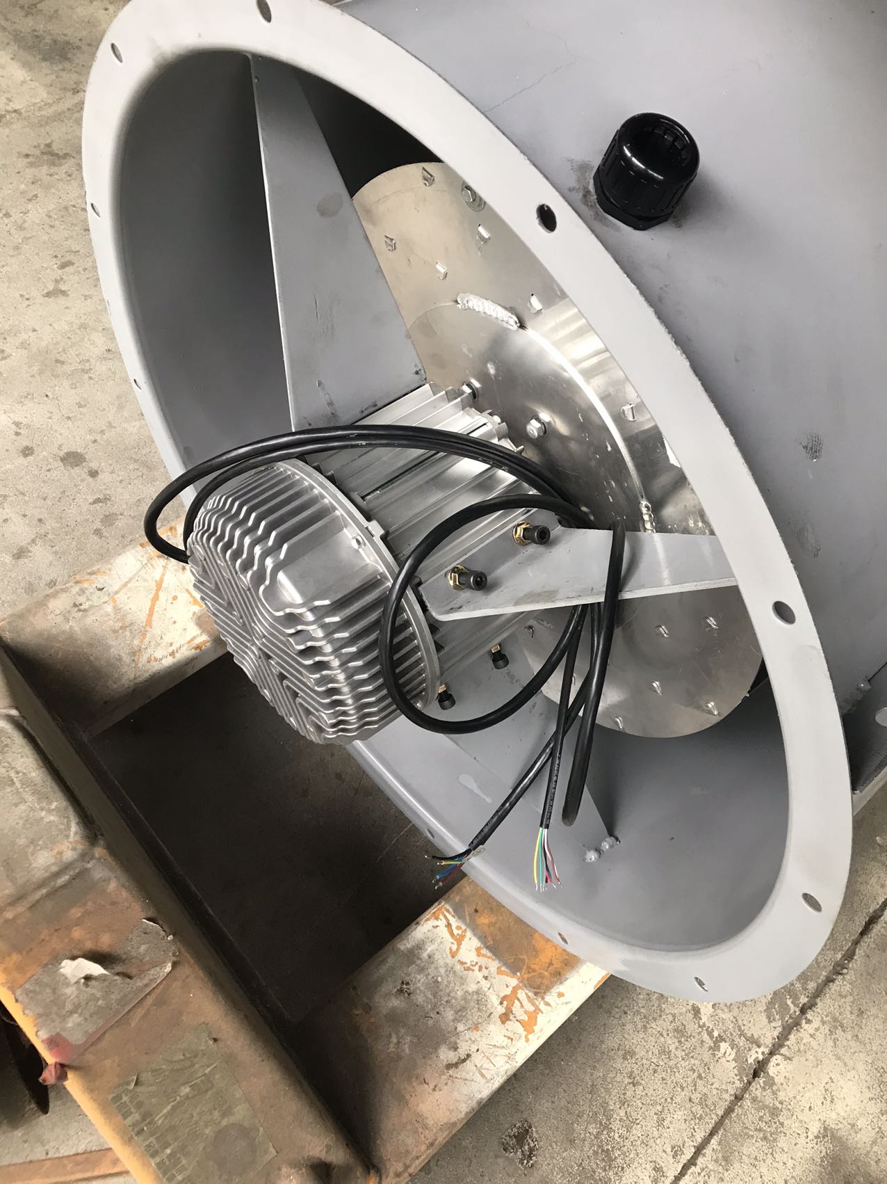
This control method proves vital for continuous-duty applications. Consider a large air handling unit. Think about critical server room ventilation. You often install an EC Centrifugal Fan in these environments. These fans must run nonstop. They also require precise speed modulation to maintain static pressure. Analog control delivers this reliability day after day.
Engineers often debate analog versus digital control methods. You should frame this comparison carefully. Do not think of it as "best versus worst." You must view it as highly application-dependent.
Analog control offers distinct advantages for widespread adoption. It boasts universal compatibility across legacy industrial hardware. It also plays nicely alongside commercial systems. Troubleshooting remains refreshingly simple. Maintenance technicians only need a standard digital multimeter. They can measure the voltage directly at the terminals. Nobody needs complex oscilloscopes to diagnose a speed failure.
However, we must apply a skeptical lens. Analog signals carry inherent vulnerabilities. Electromagnetic interference (EMI) easily corrupts unshielded lines. Strong electrical noise from nearby drives alters the voltage signal. You also face severe voltage drop across long wire runs. Resistance increases over extreme distances. The controller might send a full 10V signal. The motor might only receive 8.5V. This results in the fan running at 85% maximum speed instead of 100%.
Digital Pulse Width Modulation (PWM) solves some of these issues. You should choose PWM for micro-controller environments. Direct Arduino integrations rely heavily on digital pulses. Environments suffering from severe electrical noise also benefit from PWM. Digital signals ignore minor voltage fluctuations. However, PWM requires specific frequency matching between the controller and the motor. It demands more complex programming upfront.
| Feature | 0-10V Analog | PWM Digital |
|---|---|---|
| Troubleshooting Tool | Standard Multimeter | Oscilloscope / Logic Analyzer |
| EMI Susceptibility | High (requires shielded cables) | Low |
| Distance Degradation | Voltage drop reduces top speed | Signal typically maintains integrity |
| Legacy Compatibility | Excellent | Poor (requires converters) |
Buyers often make a dangerous assumption during procurement. They believe one controller can drive an infinite number of fans. We call this the daisy-chain challenge.
You must understand the math behind impedance and current sourcing. Every controller has a maximum source current limit. Manufacturers measure this in milliamps (mA). Every motor has a specific input impedance. It draws a small amount of current from the control line. Wiring too many fans in parallel exceeds the controller's maximum current. This causes the control voltage to drop across the entire array. Consequently, all fans run slower than commanded.
You must follow strict best practices for a successful rollout:
You must evaluate your options carefully before purchasing. Raw CFM numbers do not tell the whole story. You need reliable electronics to ensure smooth operations.
Procurement decisions require a structured approach. You must look beyond the initial sticker price. Smart investments yield long-term operational dividends.
Upfront costs remain a significant hurdle. EC motors cost more than traditional standard AC motors. They also command a premium over basic triac-controlled units. Robust analog circuitry adds manufacturing expense. You must justify this initial capital outlay to your finance team.
Operational savings quickly offset these upfront costs. You achieve massive energy reduction through precise load-matching. Fan power consumption follows the affinity laws. Running a fan at exactly 6.5V yields 65% capacity. This fractional speed uses significantly less energy during off-peak hours. It beats cycling a standard motor 100% on and then completely off.
Maintenance reduction adds another layer of savings. Zero-brush motor designs eliminate physical wear. Soft-start programming prevents sudden mechanical jerks. This combination reduces long-term wear on belts. It protects bearings and ductwork from excessive stress.
You need a clear next-step action plan. Advise your buyers to audit their current controller output capabilities. Calculate the required CFM variation carefully. Complete these steps before finalizing the purchase order.
Analog voltage control is not a plug-and-play magic bullet. However, it remains a highly effective solution. It scales brilliantly when you integrate it correctly across your facility.
You must reiterate the importance of electrical matching. Always match your controller's current capacity directly against the motor's input impedance. Failure to do so guarantees synchronization problems across your equipment.
We strongly encourage consulting an application engineer. Review your wire-run distances carefully. Map out your control topologies thoroughly. Take these steps before making large-scale purchasing commitments to guarantee operational success.
A: Yes, you can. However, you are limited by the controller's maximum milliamp output. You must also account for the combined input impedance of all connected units. Exceeding the current limit causes speed synchronization failures.
A: This depends heavily on the manufacturer. Some models drop to a 10% idle speed. Others stop rotating entirely. We often recommend a secondary power relay. This ensures zero power consumption during standby periods.
A: No, you absolutely cannot. Triac or phase-cut dimmers alter AC voltage directly. They will severely damage the internal electronics. You require a dedicated DC low-voltage control signal for these motors.
A: You can typically run wires up to 100 feet. This distance depends largely on your wire gauge. Shielded cable is strictly mandatory. It prevents severe signal drift and electromagnetic interference.


