


Views: 0 Author: Site Editor Publish Time: 2026-08-25 Origin: Site


Incorrect fan sizing in commercial and industrial ventilation systems carries a high operational penalty. You risk excessive energy consumption, premature motor wear, or insufficient air exchange. While transitioning to Electronically Commutated (EC) technology inherently improves energy efficiency, realizing the full return on investment requires exact physical and aerodynamic sizing. Engineers often assume variable speed capabilities can compensate for a poorly specified unit. However, this assumption usually results in wasted capital expenditure and acoustic issues.
This article serves as a technical evaluation guide for engineering and procurement teams. We will walk you through the process of accurately specifying the right equipment. You will learn how to match aerodynamic metrics, evaluate form factors, and avoid common implementation risks. Choosing the optimal EC axial fan for ventilation ensures your system operates flawlessly without over-engineering or under-performing.
Precision in fan sizing goes far beyond achieving basic airflow. It fundamentally impacts the financial and mechanical health of your ventilation infrastructure. Right-sizing your equipment creates immediate benefits across capital expenditure, mechanical reliability, and environmental comfort.
Right-sizing prevents bloated capital expenditure. EC motors deliver excellent efficiency at partial loads. Because of this, some procurement teams purchase significantly oversized units under the assumption they can simply dial down the speed. Buying a massive fan for a modest airflow requirement wastes your initial budget. You pay a premium for motor capacity, housing materials, and power electronics you will never utilize. Accurately sizing the fan ensures your upfront investment matches your actual operational needs, keeping your project within budget boundaries.
Operating a fan too far from its peak efficiency point on the performance curve stresses the internal components. Every fan has a Best Efficiency Point (BEP). When you force an undersized unit to work at maximum capacity continuously, you generate excess heat in the motor windings. Over time, this thermal stress degrades the motor bearings and stresses the impeller structure. Proper sizing ensures the fan operates comfortably within its ideal aerodynamic range. This reduces mechanical fatigue and extends the operational lifespan of the entire unit.
Acoustics represent a critical yet often overlooked aspect of fan selection. Poorly sized fans usually run at higher RPMs to compensate for unexpected static pressure drops. High rotational speeds dramatically increase blade pass frequency noise and turbulent airflow sounds. This introduces unacceptable noise levels into HVAC systems, which is especially problematic in commercial office spaces, hospitals, and schools. A correctly sized fan provides the required volume and pressure at lower rotational speeds, maintaining a quieter, more comfortable environment.
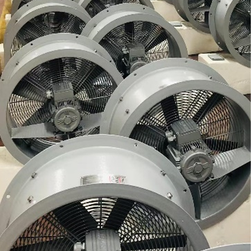
Selecting the correct ventilation equipment requires a deep understanding of fluid dynamics. You must balance the volume of air you need to move against the physical resistance of the ductwork and filters.
Your baseline calculation always begins with the required air changes per hour (ACH) for your specific facility or process. ACH dictates how many times the total volume of air in a room must be replaced in one hour. Once you know the room volume and the required ACH, you can easily calculate the necessary cubic feet per minute (CFM) or cubic meters per hour (m³/h). We recommend referencing standard industry guidelines like ASHRAE for baseline ACH targets.
Table 1: Baseline Air Changes per Hour (ACH) by Facility Type
| Facility Type | Recommended ACH Range | Primary Ventilation Goal |
|---|---|---|
| Warehouses (General) | 4 - 6 | Temperature regulation and odor control |
| Commercial Kitchens | 15 - 30 | Heat and smoke exhaust |
| Server Rooms / Data Centers | 20 - 30 | Strict thermal management |
| Manufacturing Floors | 6 - 12 | Contaminant removal and worker safety |
Airflow volume tells you how much air to move, but static pressure tells you how hard the fan must push to move it. You must map the total system resistance. This includes ductwork friction, bends, louvers, dampers, and cooling coils. Every component placed in the airstream creates a pressure drop.
Implementation Reality: Never size a system based purely on "clean filter" pressure drops. As filters accumulate dust, their resistance increases significantly. We advise engineers to size their fans based on the midpoint or "dirty filter" resistance. Failing to account for filter loading guarantees your system will under-perform months after installation.
The operating point is the exact intersection where your system's resistance curve meets the fan's performance curve. You should plot system impedance against the manufacturer’s EC fan performance curve. This helps you locate the optimal intersection. If the operating point falls too far to the left or right of the fan curve's center, you risk aerodynamic stall or inefficient energy use.
System Resistance Summary Chart
| System Component | Typical Pressure Drop (Pa) | Notes for Engineers |
|---|---|---|
| Straight Ductwork (per 10m) | 10 - 25 Pa | Varies heavily by duct diameter and air velocity. |
| Standard MERV 8 Filter (Clean) | 30 - 50 Pa | Baseline resistance. |
| Standard MERV 8 Filter (Dirty) | 100 - 150 Pa | Design operating point should account for this value. |
| Heating / Cooling Coils | 50 - 120 Pa | Dependent on fin density and air velocity. |
Aerodynamic performance means very little if the equipment cannot physically fit into your building or machinery. Evaluating the correct form factor ensures a smooth installation process.
Different applications demand different physical envelopes. Manufacturers produce distinct axial profiles to accommodate these varying installation realities.
Integration flexibility is crucial for project success. EC fans come in standard dimensions ranging from 300mm up to 900mm+ diameters. You must evaluate mounting flange configurations carefully. Wall plate designs work best for direct exterior exhaust. Grid mounts provide essential safety for exposed installations. Duct-mounted flanges allow seamless integration into existing inline HVAC networks. Verify your dimensional limits early in the design phase.
No two environments are exactly alike. The surrounding environment dictates the electrical and physical safeguards your fan requires to survive.
Modern commercial buildings experience highly variable demand. Occupancy changes throughout the day, requiring dynamic airflow adjustments. When selecting equipment for these environments, focus on control integration. Highlight the importance of 0-10V analog, PWM (Pulse Width Modulation), or Modbus RTU communication protocols. These inputs allow seamless dynamic response to Building Management Systems (BMS). The BMS can adjust fan speeds in real-time based on CO2 sensors or temperature probes, maximizing energy savings.
Industrial settings pose severe threats to unprotected electronics. You must assess environmental hazards thoroughly.
Regulatory compliance ensures baseline efficiency and safety. Ensure the selected fan meets regional standards. In Europe, the ErP (Energy-related Products) directive mandates strict efficiency minimums for motor-impeller combinations. In North America, look for AMCA (Air Movement and Control Association) certifications. Specifying certified equipment guarantees the vendor's aerodynamic claims are independently verified.
Navigating the selection process requires a structured methodology. Follow this proven five-step framework to specify the perfect unit for your project.
Even a perfectly specified fan will fail if installed incorrectly. Avoid these frequent engineering pitfalls during deployment.
The "System Effect" describes the loss of aerodynamic performance caused by poor installation conditions. Placing 90-degree duct bends, transitions, or tight dampers too close to the fan inlet or outlet destroys aerodynamic efficiency. The fan relies on a smooth, uniform velocity profile to generate pressure. Disrupting this airflow creates turbulence, drastically lowering actual CFM regardless of perfect theoretical sizing. We recommend leaving a minimum of 2.5 duct diameters of straight run before and after the unit.
Many engineers fall for the myth that sizing does not matter because EC fans are speed-controllable. This is economically wasteful. A highly oversized fan running at 20% speed operates far below its peak efficiency. You still pay for the massive motor and bulky housing upfront. Right-sizing remains imperative, using variable speed only to trim performance to daily load variations, not to fix gross specification errors.
EC motors integrate the motor and variable frequency drive into one package. These integrated electronics require adequate airflow over the motor casing for self-cooling. Operating constantly at extremely high static pressure with very low airflow restricts the cooling effect. This can cause the electronics to overheat, leading to thermal clipping where the fan artificially limits its own speed to prevent permanent damage. Always verify minimum cooling airflow requirements with the manufacturer.
Choosing the correct equipment involves a delicate balance of aerodynamic data, physical space constraints, and application-specific compliance. A highly efficient motor means little if it fights against unmapped static pressure or operates outside its optimal aerodynamic range. Proper sizing ensures you maximize energy savings, protect mechanical components, and eliminate disruptive acoustic issues.
We advise procurement and engineering teams to finalize their internal requirements thoroughly. Document your target airflow, realistic static pressure drops, required IP ratings, and exact physical dimension limits before ever requesting vendor quotes. This preparation prevents costly rework later in the project timeline.
Take the guesswork out of your next HVAC project. We prompt you to consult with technical sales engineers or utilize specific fan selection software to validate your calculated operating points before making a final purchasing decision.
A: Yes physically, but aerodynamic performance and control wiring will differ. EC units often deliver superior airflow at similar dimensions. However, because their torque characteristics differ from AC motors, re-evaluating your system curve is highly recommended to maximize the energy-saving potential of the EC technology.
A: The primary advantage is a significantly reduced physical depth. This makes them ideal for tight installations like Air Handling Units (AHUs), custom machinery enclosures, or retrofit projects. They offer comparable airflow and pressure capabilities while saving valuable system space.
A: You must sum the pressure drops of all inline components at your required airflow rate. This includes ductwork lengths, bends, filters, and grilles. Engineers typically use HVAC engineering tables, fluid dynamics software, or manufacturer pressure-drop charts to find these values accurately.
A: Unlike traditional AC motors, EC motors maintain near-peak efficiency across a much wider range of partial loads. They excel at variable speed operations. However, running them at extreme low speeds (under 10% capacity) can sometimes impact the self-cooling mechanism of the motor electronics.
