Professional manufacturer of High-quality cooling fans


Views: 0 Author: Site Editor Publish Time: 2026-08-23 Origin: Site


Upgrading ventilation components is no longer just about moving air. You must navigate strict energy compliance mandates, such as ErP and ASHRAE, while maximizing operational efficiency. While Electronically Commutated (EC) technology stands as the industry standard for efficiency, choosing the wrong configuration introduces severe risks. A poorly matched fan can cause acoustic issues, integration bottlenecks, or premature system failure. You need a reliable approach to avoid these costly engineering missteps.
This guide provides a direct, engineering-focused framework for evaluating and specifying the exact components you need. We strip away marketing claims so you can focus on operational realities and aerodynamic constraints. By reading this, you will learn how to match system impedance to fan performance curves. You will also understand how to specify the right EC fan for HVAC applications with confidence.
Host equipment defines your physical and aerodynamic constraints. You cannot select a fan in a vacuum. The internal geometry of your system dictates airflow resistance. We must evaluate these physical realities before looking at specific fan models.
Different HVAC systems demand completely different aerodynamic profiles. Understanding your host equipment prevents catastrophic selection errors.
You must establish clear success metrics before shortlisting any fan. Vague goals lead to poor procurement decisions. Define your exact targets mathematically.
First, establish energy reduction targets. Do not just look at peak load efficiency. Calculate expected savings during partial-load operation. You might target a 30% reduction in fan energy when the system runs at half capacity. EC motors excel in these low-speed scenarios.
Second, define strict acoustic limits. Specify the exact decibel (dBA) limits at specific distances. A fan might sound quiet at three meters but create a low-frequency hum that penetrates nearby walls. Define these parameters early to rule out unsuitable aerodynamic designs.
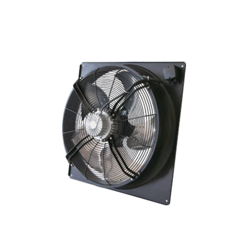
Choosing between axial and centrifugal designs represents the most critical aerodynamic decision. Getting this wrong guarantees system failure. You must match the impeller design to your specific impedance curve.
Axial fans move air parallel to the motor shaft. They act like airplane propellers. They push massive volumes of air highly efficiently. However, they struggle against resistance.
We specify an HVAC EC Axial Fan for heat pumps, condensing units, and agricultural ventilation. These applications offer mostly free air delivery. The fan operates near the bottom of the pressure curve. If you place an axial fan behind a dense HEPA filter, it will stall. The blades will simply churn the air, creating noise without actual flow.
Centrifugal fans pull air in axially and exhaust it radially. This 90-degree turn builds significant kinetic energy. This energy translates directly into static pressure.
These fans overcome high resistance effortlessly. We use them in AHUs, ductless systems, and packaged rooftop units (RTUs). When your air must travel through long ductwork or dense filtration media, you need a centrifugal or plug fan. They maintain steady airflow even as system impedance increases.
Use the rule of thumb for crossing system impedance curves with fan performance curves. The intersection marks your duty point. You must ensure this duty point falls squarely in the fan’s peak efficiency zone. Avoid selecting a fan where the duty point sits on the far edges of the performance curve.
| Application Type | Recommended Fan Type | Primary Strength | Key Limitation |
|---|---|---|---|
| Heat Pumps / Condensers | Axial Fan | High volume air movement at low energy | Stalls under high static pressure |
| AHUs (Filtered Air) | Centrifugal / Plug Fan | Overcomes heavy filter/coil resistance | Lower sheer volume compared to axial |
| Data Center CRACs | Backward Curved Centrifugal | Precise control under variable loads | Requires larger installation depth |
| Agricultural Exhaust | Large Diameter Axial | Moves massive air at free delivery | Highly susceptible to wind interference |
Aerodynamics represents only the first step. You must evaluate the electronic and mechanical dimensions to ensure long-term reliability. Ignore generic marketing brochures. Focus entirely on hard engineering data.
Do not size fans based on peak CFM alone. Manufacturers often advertise the absolute maximum airflow. This number reflects zero static pressure. Your system will never operate at zero static pressure.
You must evaluate the fan curve against actual static pressure. Measure this in inches of water gauge (in. w.g.) or Pascals (Pa). Plot your exact required airflow against this resistance. Furthermore, ensure the selected fan operates efficiently at partial loads. HVAC systems rarely run at 100% capacity. EC motors deliver their primary energy advantages during these partial-load phases.
EC fans require precise control signals. You must verify required control inputs before installation. Older Building Management Systems (BMS) often use simple 0-10V analog signals or PWM (Pulse Width Modulation). These work well for basic setups.
Modern setups demand digital bus communication. Protocols like Modbus RTU or BACnet allow daisy-chaining. This reduces wiring complexity. Digital buses also provide real-time feedback. You can monitor RPM, power consumption, and error codes directly from the control room.
Assess whether you need closed-loop control. Many advanced EC fans feature built-in PID controllers. You connect pressure or temperature sensors directly to the fan. The fan manages its own speed automatically, bypassing external controllers entirely.
Operating environments destroy unprotected electronics. You must specify the correct Ingress Protection (IP) rating. Standard indoor units usually survive with IP54 or IP55 ratings. These handle basic dust and light splashes.
Outdoor or highly corrosive environments demand much more. Specify IP68 for extreme locations. Request special epoxy coatings for stators and circuit boards. Salt spray near coastal areas quickly corrodes standard metals.
Always verify bearing life expectations. Ask the manufacturer for L10 lifespan data. This metric indicates when 10% of a sample group might fail. Ensure they base this data on realistic operating temperatures, not just ideal lab conditions. Hot environments degrade bearing grease rapidly.
Noise complaints ruin successful installations. You must evaluate sound power levels across the entire operating spectrum. A fan might run quietly at 20% speed but emit a piercing whine at 80% speed.
Consider advanced blade designs. Manufacturers now mold serrated trailing edges into the fan blades. These serrations break up trailing air vortices. This reduces tonal noise significantly. Use these specialized designs in noise-sensitive zones, such as hospitals or residential heat pumps.
Engineers often face pushback on the initial cost of EC fans. You must justify this specification clearly. The technological differences between standard AC, standard DC, and EC motors translate directly into measurable performance gaps.
Standard AC motors rely on Variable Frequency Drives (VFDs) for speed control. This combination works, but it suffers heavy drawbacks. AC motors lose significant efficiency at low speeds. The VFD also generates electrical harmonic noise, which overheats the motor.
EC motors solve this completely. They maintain incredibly high efficiency across their entire speed range. You often see efficiencies up to 90%. When the system scales down to meet a lighter thermal load, the EC fan scales its power consumption linearly. You capture massive energy savings during off-peak hours.
Standard DC fans require external commutation. You must install separate circuit boards to flip the magnetic fields. This adds wiring complexity and increases the risk of component failure.
EC fans integrate everything. The motor, the commutation electronics, and the control logic sit inside a single unit. This plug-and-play architecture drastically reduces installation complexity. Fewer connections mean fewer potential points of failure. The onboard electronics also monitor internal temperatures, protecting the motor from thermal overload.
Traditional AC fan setups consume enormous space. You have a bulky motor, a belt drive system, and a separate fan scroll. These components dictate large cabinet sizes.
Most EC fans utilize an external rotor design. The motor sits directly inside the impeller hub. This eliminates belts, pulleys, and external shafts. The result is a significantly more compact profile. You can design slimmer air handling units. You can pack more cooling capacity into smaller data center floor plans.
Theory always looks perfect on paper. The field presents messy realities. You must anticipate integration risks before contractors begin installation. Addressing these risks early prevents costly project delays.
Many contractors believe EC fans act as direct drop-in replacements. This is a dangerous myth. You cannot simply pull out an old belt-driven fan and bolt an EC fan in its place.
You must address the physical reality of the bulkhead wall. EC fans usually feature a smaller footprint than legacy AC equipment. If you leave gaps around the new fan, air takes the path of least resistance. It loops back around the fan instead of pushing down the ductwork. You must design and install structural blanking plates. These metal plates seal the bulkhead, forcing all air directly through the new impeller.
Large arrays of EC fans impact your building's electrical grid. The internal electronics draw power non-linearly. This can introduce harmonic distortion back into the power supply.
You must discuss potential issues with active power factor correction (PFC). Look for fans equipped with active PFC to keep harmonic distortion well below standard limits (such as IEEE 519). If you install fifty large EC fans in a single facility without PFC, you risk tripping main breakers or damaging sensitive nearby electronics.
Commissioning reveals the most common installation errors. Contractors frequently rush the wiring phase. They run low-voltage control cables (like 0-10V or Modbus lines) right alongside high-voltage power lines.
This creates electromagnetic interference. The high-voltage lines induce noise onto the control signals. Your fan might speed up and slow down erratically. The BMS might lose communication entirely. Always specify shielded control cables. Demand strict physical separation between high-voltage and low-voltage cable trays.
Selecting the right components requires strict attention to detail. It is a precise balance of matching aerodynamic capabilities to system impedance while ensuring seamless electronic integration. You cannot rely on broad assumptions or peak airflow numbers. You must dive into the specific static pressure curves, acoustic limits, and digital communication requirements of your host equipment.
To move forward successfully, follow these critical next steps:
A: Yes, you can use standard thermostats via simple relays or direct 0-10V analog signals. However, basic on/off thermostats limit the overall energy savings. Using a Building Management System (BMS) or a dedicated PID controller maximizes efficiency by continuously adjusting fan speeds to match real-time thermal demand.
A: The lifespan generally spans 40,000 to 70,000 hours. This depends heavily on operating temperatures and bearing quality. High ambient heat degrades internal grease faster. Always emphasize checking L10 data, which provides a statistical baseline for when 10% of units might fail under specific loads.
A: No, you do not need an external VFD. EC fans feature integrated electronics built directly into the motor housing. These onboard electronics handle all speed control and commutation internally. This design eliminates the cost, wiring complexity, and cabinet space requirements of traditional external VFDs.
A: Yes, they excel in outdoor environments provided they are specified correctly. You must request the proper IP rating (such as IP55 or IP68) to protect against water and dust. Furthermore, specify corrosion-resistant materials and specialized epoxy coatings for the electronics to survive rain and coastal salt spray.
