


Views: 0 Author: Site Editor Publish Time: 2026-08-22 Origin: Site


The transition from analog control (0-10V/PWM) to digital communication in HVAC systems is no longer optional for modern smart buildings. Facility managers face intense pressure to optimize energy use and maintain pristine indoor air quality. You can no longer rely on blind, one-way signals to manage complex environments. Intelligent ventilation requires continuous, bi-directional data flow. You need more than just simple speed commands. Your system must handle real-time fault reporting, RPM feedback, and granular energy consumption metrics.
Deploying an RS485 EC fan enables scalable, sensor-driven ventilation control systems. It acts as the digital backbone of responsive building automation. However, realizing its full return on investment requires strict attention to detail. You must carefully manage protocol integration, holding register mapping, and network topology. This guide explores the critical implementation steps needed for success. You will learn how to bridge mechanical air movement and digital building intelligence effectively.
Building operators constantly seek ways to improve HVAC performance while reducing operational friction. Moving to digital communication provides a robust foundation for automated building management.
Legacy analog systems relying on 0-10V signals suffer from inherent physical limitations. You will often experience voltage drop over long cable runs. A controller might send a 10V signal, but the fan only receives 8.5V due to line resistance. This results in underperforming ventilation. Furthermore, analog control is fundamentally unidirectional. You operate the system blindly. The master controller sends a speed command but receives no confirmation. It cannot verify if the fan is spinning, stalled, or damaged. This lack of diagnostic capability forces maintenance teams into a reactive posture.
Digital communication transforms fans from simple mechanical components into intelligent network nodes.
Predictive Maintenance: Facility managers gain unprecedented access to internal motor data. The RS485 network transmits real-time operating temperatures, cumulative running hours, and rotor lock alerts. You can monitor these variables constantly. This visibility allows teams to shift from reactive emergency repairs to planned, predictive maintenance. You can replace bearings or clear blockages before a catastrophic failure disrupts building operations.
Cost of Installation: Analog setups require dedicated home-run wiring for every single fan. This consumes massive amounts of copper and labor. RS485 technology replaces these cumbersome analog bundles with a serialized daisy-chain topology. You route a single twisted-pair cable from one fan to the next. This drastically reduces wiring complexity, cable tray congestion, and upfront installation costs.
You must measure a deployment against clear operational metrics. A successful installation significantly reduces overall HVAC energy consumption. It achieves this by matching fan speed precisely to real-time environmental demand. Furthermore, a highly optimized digital setup should maintain 99.9% uptime on the communication bus. Signal stability prevents unexpected system shutdowns and ensures continuous climate control.
Selecting the right hardware dictates the long-term stability of your ventilation network. You must evaluate mechanical efficiency alongside digital maturity.
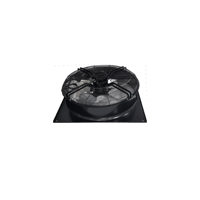
Digital control means little if the underlying hardware wastes power. Look for highly efficient commutation electronics embedded directly into the motor housing. You must also evaluate optimal blade design for your specific application. For example, specifying an EC Axial Fan makes sense for specific exhaust or supply air volume requirements where static pressure demands are moderate. Always verify the operating temperature range of the integrated electronics. Check the IP rating to ensure the fan can withstand dust and moisture in harsh mechanical rooms.
The internal communication board serves as the brain of the fan.
Modbus RTU Compliance: Ensure the fan uses the standard Modbus RTU protocol. Avoid proprietary, closed-loop RS485 protocols. Closed systems lock you into a single manufacturer ecosystem. Standard Modbus RTU guarantees interoperability across various BMS platforms and third-party controllers.
Register Map Transparency: A reliable supplier will provide a clear, standardized holding register map. This documentation details exactly how to communicate with the device. It should list every Address, Read/Write status, and Data Type clearly. Poor documentation leads to endless commissioning delays.
Typical Modbus Holding Register Structure
| Register Address | Function Description | Read/Write Capability | Data Range / Type |
|---|---|---|---|
| 40001 | Target Fan Speed Setting | Read / Write | 0 - 10000 (0-100%) |
| 40002 | Actual RPM Feedback | Read Only | 0 - Maximum RPM |
| 40003 | Internal Motor Temperature | Read Only | Degrees Celsius (INT16) |
| 40004 | Fault Code Status | Read Only | 0 = Normal, 1+ = Error Codes |
Network disruptions happen. A severed cable or a failed master controller can instantly drop the RS485 signal. Evaluate the fan’s default behavior upon communication loss. A well-designed digital fan allows you to program a failsafe state. It might maintain the last known speed to prevent sudden pressure drops. Alternatively, you can configure it to drop to 0% or ramp up to a preset safe speed (like 50%) to guarantee minimal ventilation. This feature is critical for safety-compliance in laboratories and industrial facilities.
An RS485 network reaches its full potential when integrated with intelligent environmental sensors. This synergy creates an automated, self-adjusting climate ecosystem.
Modern building standards emphasize Demand-Controlled Ventilation (DCV). This strategy reduces energy waste by ventilating spaces based purely on actual occupancy and air quality. You achieve this by mapping fan speed curves to real-time inputs from external smart controllers. These controllers continuously monitor CO2, PM2.5, and VOC levels.
The logic flow operates in a continuous, automated loop:
This closed-loop system ensures the fan never spins faster than necessary. It slashes energy consumption during off-peak hours while aggressively clearing pollutants during peak usage.
Many modern smart buildings rely on wireless cloud infrastructure. You must bridge these modern wireless protocols with robust wired networks. Modern edge controllers act as essential gateways here. They convert cloud-based Wi-Fi or mobile app commands into localized RS485 signals for the fan network. For example, a facility manager can adjust setpoints remotely via a Tuya-enabled app. The cloud server pings the local gateway over Wi-Fi. The gateway instantly translates this packet into a Modbus RTU command. It pushes the instruction down the RS485 wire to the specific fan address. This hybrid architecture delivers cloud convenience without sacrificing localized, hardwired reliability.
Theoretical digital architecture often clashes with harsh physical realities. You must navigate strict electrical and networking rules to prevent unstable communications.
RS485 networks require strict adherence to daisy-chain routing. You must wire the network sequentially from device A to device B, then to device C. Avoiding star or ring topologies is absolutely critical. Star configurations create multiple cable branches. These branches cause signal reflection and impedance mismatches. Reflected signals bounce back down the wire and corrupt incoming data packets. This leads to dropped commands and erratic fan behavior.
Every node on a Modbus network requires a unique identifier. You must assign a standard address ranging from 1 to 247 during pre-commissioning. Addressing conflicts represent a massive technical risk. If two fans share address 15, the master controller cannot decipher their responses. Their data packets will collide on the bus. This creates an unreadable data storm. Best practice dictates creating a detailed network map. Assign and document all addresses physically on the fan housing before mounting them in difficult-to-reach ceilings.
Digital signals are highly susceptible to physical degradation. Protecting the physical layer is non-negotiable for system uptime.
You cannot buy digital fans off the shelf without a rigorous vetting process. A systematic procurement approach prevents expensive integration failures later.
Your physical environment dictates the hardware specifications. Is this deployment for a sensitive cleanroom, a high-density data center, a modular AHU, or general commercial ventilation? High-density environments require fans with high static pressure capabilities. Form factor also matters. An axial fan suits wide, open exhaust applications, while a backward-curved centrifugal impeller handles the high resistance of HEPA filters.
Never assume plug-and-play functionality. You must cross-check the fan’s default communication parameters with your existing master controller. Verify the default baud rates (typically 9600 or 19200) and parity options (None, Even, or Odd). A mismatch in baud rate renders communication impossible. Some cheaper fans lock their baud rates, which forces you to reprogram your entire BMS to match the fan. Always demand configurable communication parameters.
Knowledge is your best defense against integration bottlenecks. Never procure an RS485 fan without first reviewing the technical data sheet and the Modbus communication manual. Ensure the supplier provides a comprehensive holding register map. If the manufacturer hesitates to share their protocol manual, they likely use a proprietary system. Walk away from closed systems.
Large-scale deployments carry massive financial risk. We strongly recommend purchasing a single unit and a compatible smart controller first. Execute a bench test to verify network handshakes and sensor logic. Confirm the fan ramps up smoothly when CO2 levels rise. Check if the fault codes trigger correctly when you simulate a rotor lock. Successful pilot testing validates your programming logic before you commit to a facility-wide rollout.
Integrating an RS485 digital fan bridges the critical gap between mechanical air movement and digital building intelligence. It moves your infrastructure away from blind, wasteful analog systems. You unlock advanced energy savings, precise demand control, and proactive diagnostics. Facility managers can finally see exactly what happens inside their HVAC networks in real time.
While the upfront hardware cost may be marginally higher than basic analog units, the broader financial picture strongly favors digital control. The massive reduction in wiring complexity slashes installation costs. When combined with lifecycle savings from demand-controlled ventilation and predictive maintenance, the digital approach delivers a rapid and compounding return on investment.
Your next actionable step is to consult directly with a certified ventilation engineer. Ask them to review your site’s specific Modbus architecture. You should then request a detailed fan selection curve matched exactly to your required operating point to ensure maximum aerodynamic efficiency.
A: Under ideal conditions with proper shielded cabling and termination, an RS485 network can reach up to 1,200 meters (4,000 feet). However, baud rate and environmental EMI can reduce this practical limit. Lower baud rates typically allow for longer cable runs.
A: A 0-10V fan receives a one-way analog voltage signal to dictate speed. An RS485 fan uses a digital protocol (usually Modbus) for two-way communication, allowing it to receive speed commands and send back data like RPM, power consumption, and error codes.
A: Yes. Each fan is assigned a unique Modbus address (typically 1 to 247). The master controller can send specific commands to individual fans or broadcast commands to all fans on the daisy-chained network.
A: You need a master device capable of Modbus RTU communication over RS485. This can be a dedicated smart ventilation controller, a PLC, or a centralized Building Management System (BMS).
