


Views: 0 Author: Site Editor Publish Time: 2026-08-29 Origin: Site


Achieving optimal energy efficiency and acoustic performance in modern HVAC design relies on precise component selection. You cannot simply rely on broad technology upgrades. Engineers must scrutinize individual elements. This guarantees systems meet demanding performance targets.
Electronically Commutated (EC) technology stands as the industry standard for high-efficiency air movement. However, incorrectly sizing an EC fan for ventilation system applications can easily negate expected energy savings. Mistakes introduce major control bottlenecks. They also severely shorten overall equipment lifespan.
This guide provides an evidence-based framework to evaluate and size these units. We will show you how to select the exact fan for various environments. You will explore commercial air handling units (AHUs) and heavy-duty industrial setups. You will learn to navigate complex aerodynamic requirements, environmental constraints, and intelligent integration protocols.
Match the Operating Point: Selection must be based on the intersection of the system resistance curve and the fan’s peak efficiency zone, not just maximum free-air metrics.
Control Integration is Critical: A high-efficiency motor is useless without matching control protocols (0-10V, PWM, or Modbus RTU) that integrate seamlessly with your Building Management System (BMS).
Account for Real-World Environments: IP ratings, operating temperatures, and acoustic constraints dictate housing and impeller material choices.
You must define the exact Volume Flow Rate required. Engineers measure this in cubic feet per minute (CFM) or cubic meters per hour (m³/h). This metric dictates the total air volume needed for a specific building zone or industrial process. You base this calculation on sensible heat loads, latent moisture removal, or mandated air change rates (ACH).
Next, calculate the Total System Resistance. You measure static pressure in Pascals (Pa) or inches of water gauge (inWG). Account for all internal components. Factor in heating coils, cooling coils, and mixing dampers. Analyze your ductwork complexity, including elbows and transitions. Always anticipate future system degradation. We call this the "dirty filter allowance." Adding 0.5 to 1.0 inWG ensures the fan maintains airflow even as filters clog over time.
You must identify where your system resistance curve intersects the fan performance curve. The fan curve plots airflow on the x-axis and static pressure on the y-axis. The system curve rises exponentially as a parabola. The precise intersection represents your true operating point. It dictates your real-world energy consumption.
Expertise Note: Never select a unit where the operating point falls in the aerodynamic stall region. Avoid the extreme right side of the performance curve. The stall region causes buffeting, severe vibration, and premature bearing failure. Operating on the extreme right leads to massive inefficiency and destructive aerodynamic noise.
Engineers should factor in a 10-15% safety margin for both airflow and static pressure. This buffer handles unexpected system variations. It compensates for slight ductwork modifications during construction. Importantly, a modest 15% margin keeps the unit within its optimal efficiency range.
Avoid excessive oversizing. Adding a 30% or 40% safety margin pushes the operating point down. It forces the motor to run continuously at very low speeds. This wastes energy and reduces the inherent benefits of electronic commutation.
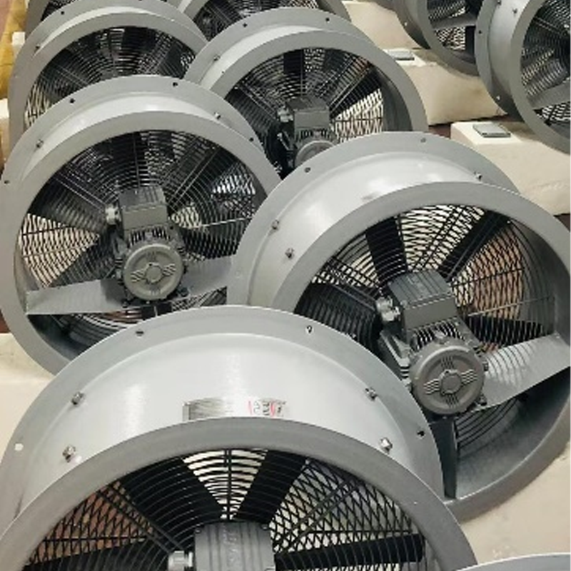
Commercial spaces demand exceptional acoustic performance. You must focus on sound power levels (LwA) rather than just sound pressure (LpA). Always verify acoustic data at the actual operating point. Free-air acoustic numbers heavily mislead engineers. Examine the blade pass frequency to avoid low-frequency rumble, which penetrates drywall easily.
Consider spatial limitations inside existing mechanical rooms. Backward-curved plug fans offer a highly compact footprint. They lack bulky scroll housings. This makes them ideal for tight AHU retrofit projects. You can stack them vertically or horizontally to maximize space.
Extreme temperatures demand careful evaluation. Always check the motor derating curve. Manufacturers program EC motors to slow down automatically. They do this to protect internal electronics if ambient environments exceed 40°C (104°F). If your process runs hot, you must size the fan to deliver required airflow at the derated speed.
Specify appropriate Ingress Protection (IP) ratings. IP54 ratings protect internal components from standard dust and splashing moisture. IP55 ratings protect against low-pressure water jets. You must ensure motor longevity in harsh industrial zones, agricultural facilities, or outdoor heat pump enclosures.
Compare your impeller material options carefully. Galvanized steel provides heavy-duty strength for high-pressure industrial exhausts. However, its heavy mass increases motor wear. Aluminum impellers reduce overall weight. They resist rust well in marine environments.
Composite or polymer impellers resist aggressive chemical corrosion. They suit natatoriums or wastewater treatment plants perfectly. Specifying a durable ventilation EC fan requires matching the impeller material directly to the airstream chemistry. Composite materials also offer complex 3D-profiled blades, maximizing aerodynamic efficiency.
Assess your communication protocols early in the design phase. Standard analog controls work well for basic setups. You can use simple 0-10V or 4-20mA signals for standard demand-controlled ventilation. A central controller varies the voltage to adjust motor RPM linearly.
Advanced diagnostics require digital protocols. Multi-fan arrays rely heavily on Modbus RTU or BACnet. These digital networks allow two-way communication. They transmit exact RPM, power consumption data, and specific fault codes directly to the facility manager's dashboard.
Determine your direct control needs. Many modern units include integrated PID (Proportional-Integral-Derivative) controllers on the motor itself. They respond directly to external duct pressure transducers, thermistors, or room CO2 sensors. You can bypass the central BMS entirely for local control.
The onboard PID algorithm calculates the exact speed required. It eliminates speed hunting and oscillation. This simplifies local zone control and reduces field wiring complexity.
Implementation Reality: Large fan walls draw substantial power. You must evaluate if built-in active PFC is necessary. Electronic commutation naturally generates harmonic distortion on the facility's electrical grid. High Total Harmonic Distortion current (THDi) overheats local transformers.
Utility companies often fine facilities for poor power factors. Active PFC keeps THDi below 5%. It ensures the system draws clean, efficient power without requiring external harmonic filters.
Comparison of EC Fan Control Protocols
Protocol Type | Network Complexity | Best Use Case | Data Feedback Capabilities |
|---|---|---|---|
0-10V Analog | Low | Single fans, simple local exhaust | None (One-way speed command only) |
PWM (Pulse Width Modulation) | Low | OEM equipment, small heat pumps | Tachometer pulse output (RPM only) |
Modbus RTU | Medium | Industrial arrays, retrofits | Full diagnostics, power draw, fault codes |
BACnet MS/TP | High | Large commercial building HVAC | Full integration into central facility systems |
Upgrading systems provides massive physical benefits. Modern technology eliminates the need for external Variable Frequency Drives (VFDs). The drive electronics sit inside the motor housing. You also remove heavy belt-drive systems, pulleys, and external bearings. This eliminates belt dust and routine mechanical greasing.
Assess structural requirements carefully before demolition. You will replace heavy, belt-driven forward-curved scroll fans. You will install lighter, direct-drive plug fan arrays. Engineers call these Fan Walls. Fan walls offer N+1 redundancy. If one motor fails, the remaining units speed up automatically to maintain duct pressure.
Removing external VFDs also eliminates long runs of expensive shielded cable. VFDs generate electromagnetic interference (EMI). Integrated motors keep high-frequency switching internal, protecting nearby sensitive facility electronics.
Energy regulations change rapidly across the globe. You must ensure your selected units comply with regional rules. Europe enforces strict ErP 2015 efficiency minimums. Manufacturers refer to this as the Fan Motor Efficiency Grade (FMEG).
North America relies on ASHRAE 90.1 standards. These codes increasingly utilize the Fan Energy Index (FEI) to mandate baseline performance. Selecting compliant hardware guarantees a high baseline motor efficiency. It also prevents costly delays during local building inspections and commissioning sign-offs.
Does the manufacturer provide certified data? Never trust theoretical marketing numbers. Look for AMCA 210 certification for aerodynamic performance. Demand AMCA 300 certification for acoustic testing results. Third-party verification prevents underperforming systems.
Air density changes performance drastically. Do they offer proprietary selection software? You need tools to model performance across various altitudes. A system in Denver operates differently than one at sea level. The software must calculate speed adjustments for extreme cold or high humidity environments.
Equipment delays kill construction schedules. Are critical components modular? Ensure the supplier manages inventory effectively. Local assembly hubs and modular impeller designs allow vendors to meet your specific project deadlines without long overseas shipping waits.
Demand a minimum two-year warranty for commercial applications. Look for accessible technical support. Commissioning communication protocols often requires expert guidance. Modbus addressing and baud rate mismatches frequently trip up field contractors. Accessible factory engineers save hours of troubleshooting.
On-site wiring causes major errors. Reversed polarity or loose terminals destroy electronics. Does the unit arrive pre-wired? Ensure it comes pre-programmed from the factory with your required setpoints. Extensive field configuration wastes expensive labor hours. Factory-tested assemblies guarantee immediate operational readiness.
Move beyond basic metrics: Align your selection with precise aerodynamic operating points. Account for environmental realities rather than relying solely on maximum CFM ratings.
Filter out underperforming hardware early: Discard options failing your static pressure needs at partial speeds. Evaluate remaining units based on long-term reliability and BMS integration ease.
Prioritize digital integration: Ensure the internal electronics communicate flawlessly with your chosen protocol. Proper data feedback prevents unexpected facility downtime.
Consult engineering professionals: Run your system resistance calculations through dedicated selection software. Rely on data rather than rough estimations.
Verify physical dimensions: Measure existing AHU bulkheads before ordering. Ensure fan walls fit through existing mechanical room doors during retrofits.
A: Yes, but you must adapt the physical infrastructure. You need new mounting plates and bulkhead seals. You must also bypass old electrical components like external VFDs. Direct drop-in replacements exist for smaller units. However, optimizing larger systems usually requires transitioning from a single large unit to a multi-fan array setup.
A: Size the unit to handle the maximum design load first. Then, rigorously verify the efficiency curve at the 50-70% load range. Demand-controlled systems spend the vast majority of their operational life running at partial speeds. A unit running efficiently at part-load yields the highest energy savings over time.
A: Mechanically, they operate much quieter. They lack noisy belts, squeaking pulleys, and loud contactors. Optimized motor commutations reduce electrical hum. However, aerodynamic noise remains a major factor. It depends entirely on proper sizing. You must avoid high-velocity airflow restrictions and turbulent duct transitions to achieve true acoustic benefits.
