


Views: 0 Author: Site Editor Publish Time: 2026-09-06 Origin: Site


Upgrading from traditional AC motors to Electronically Commutated (EC) technology is now a standard engineering practice. Modern facilities demand smarter air movement solutions. Yet, this equipment transition is rarely a simple component swap. Mis-specifying an EC fan for industrial ventilation often leads to premature motor failure, complex integration nightmares, or wasted capacity. Superior aerodynamic efficiency means nothing if the unit mismatches your duct resistance. You also face severe risks if you deploy standard motors in highly corrosive environments. You need a rigorous, evidence-based approach to system design.
This guide provides facility managers, HVAC engineers, and system designers a clear framework for equipment selection. You will learn how to evaluate aerodynamic operating points accurately. We will help you navigate complex physical form factors. We will also explore environmental compliance standards and best practices for seamless building management integration. These steps ensure you select the exact ventilation system your facility requires.
Fan selection must be dictated by the specific operating point on the performance curve, not peak airflow or static pressure claims.
Form factor matters: Axial fans suit high-volume/low-pressure needs, while backward-curved centrifugal fans dominate high-pressure ducted systems and AHUs.
Environmental compliance (IP ratings, ATEX/explosion-proof certifications) is non-negotiable in harsh industrial settings.
Native BMS integration (Modbus/BACnet) eliminates the need for external VFDs, but requires upfront electrical infrastructure planning.
Many system designers make a critical early mistake. They rely solely on the maximum CFM or static pressure ratings printed on a spec sheet. This approach consistently leads to underperforming systems. Industrial ventilation requires sustained performance against specific system resistance. You cannot treat airflow and pressure as isolated metrics.
Airflow and static pressure share an inverse relationship. As resistance increases, the volume of delivered air decreases. You must calculate the actual system resistance accurately. This resistance includes every bend in your ductwork. It includes friction from filters, heating coils, and protective dampers. Once you quantify this total resistance, you understand the exact physical barrier your fan must overcome.
You must map your required duty point directly onto the manufacturer’s fan curve. The duty point represents your target airflow intersecting your calculated static pressure. Locate this exact spot on the X-Y axis graph.
You should select a fan operating efficiently at this specific point. Pay close attention to partial-load performance. Most modern ventilation systems rarely run at 100% capacity around the clock. Your selected unit must maintain high aerodynamic efficiency when scaled back to 60% or 80% speed.
Avoid the temptation to select an undersized unit. Running a smaller fan at maximum RPM might theoretically meet your airflow needs. However, this strategy frequently fails occupational noise compliance standards. High-velocity air generates significant turbulence and noise. A larger fan running at a slower speed delivers the same air volume quietly. This protects workers and meets strict environmental health regulations.
Physical form factors dictate how air moves through your facility. You must match the physical configuration to your engineered application. Selecting the wrong housing or impeller style severely limits performance. Let us break down the primary solution categories.
Axial fans move air parallel to the motor shaft. They excel at moving massive amounts of air quickly. You will find them heavily utilized in general warehouse exhaust systems. They also dominate cooling towers and large heat exchangers.
However, axial designs have strict limitations. They demonstrate poor performance against high static pressure. If your system relies on long, winding ductwork, an axial fan will stall and fail to push air through the barriers.
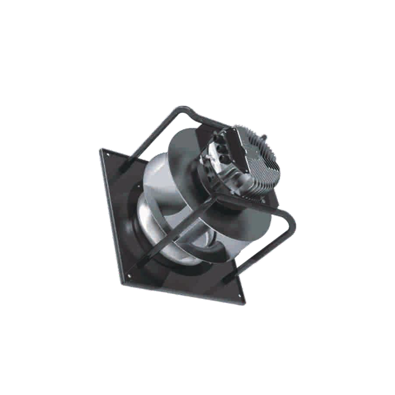
Backward-curved centrifugal designs draw air in axially and expel it radially. This design is robust and highly adaptable. An Industrial EC Fan featuring this configuration is the premier choice for high-pressure systems. You will install them in complex ductwork and custom Air Handling Units (AHUs).
These units offer distinct advantages. They feature non-overloading power characteristics. The motor will not burn out if system resistance drops unexpectedly. They also deliver higher aerodynamic efficiency in remarkably tight spaces.
Engineers increasingly rely on EC fan grids or fan walls. A fan array utilizes multiple smaller fans operating in parallel. This replaces one massive traditional blower. Fan arrays provide built-in redundancy. If one motor fails, the others increase speed slightly to maintain total airflow. They also solve severe physical space constraints during large-scale retrofits.
Configuration Comparison Chart
Feature | Axial EC Fans | Backward-Curved Centrifugal EC Fans |
|---|---|---|
Primary Application | Cooling towers, warehouse exhaust | AHUs, ducted ventilation |
Airflow Volume | Extremely High | Moderate to High |
Static Pressure Capability | Low to Moderate | Very High |
Space Requirement | Requires short depth | Requires radial discharge space |
Industrial environments are notoriously hostile. They expose delicate equipment to fine dust, heavy moisture, caustic chemicals, and extreme ambient heat. Survivability is just as critical as aerodynamic efficiency.
You must establish a strict baseline for environmental protection. Industrial applications demand specific IP ratings to prevent rapid failure.
IP54: The absolute minimum for general industrial use. It protects against splashing water and harmful dust accumulation.
IP55: Better suited for semi-exposed environments. It withstands low-pressure water jets from any direction.
IP68: Mandatory for severe washdown environments. You need this rating for food and beverage processing facilities where equipment is completely submerged or power-washed daily.
Material selection dictates operational lifespan. If your facility processes chemicals or experiences high humidity, standard steel will rust quickly. You should specify coated aluminum impellers. Consider composite plastics for lighter-duty corrosive environments. Always demand stainless steel hardware for brackets and mounting plates in aggressive atmospheres.
You must address the regulatory realities of explosive environments. Facilities handling combustible dust or flammable gases face strict rules. Standard EC motors rarely comply with strict ATEX requirements out of the box. You must specify specialized explosion-proof enclosures. The motor housing must contain any internal spark to prevent a catastrophic facility explosion.
Extreme heat is the primary enemy of EC technology. EC motors integrate internal electronic controllers directly onto the motor backing. These electronics are highly sensitive to extreme ambient heat. Always check the maximum allowable ambient temperature. A standard AC motor might survive 80°C ambient air, but a standard EC motor controller often limits out around 50°C to 60°C. You may require remote-mounted electronics for high-heat extraction systems.
The primary commercial advantage of EC technology is built-in intelligence. These units feature integrated speed control. You completely eliminate the need for external Variable Frequency Drives (VFDs). This simplifies installation and reduces physical footprint.
You can control these systems using two primary methods. Basic setups often rely on analog signals. A standard 0-10V or PWM signal works perfectly for localized control. You simply turn a dial to adjust the fan speed.
However, modern facilities require advanced digital protocols. Modbus RTU and BACnet MS/TP allow for seamless Building Management System (BMS) integration. Digital daisy-chaining connects dozens of fans onto a single communication wire. The BMS can monitor RPM, power consumption, and error codes for every single unit in real time.
You can wire EC fans directly to environmental sensors. This creates closed-loop, demand-driven ventilation systems.
Pressure Sensors: Maintain constant duct pressure as filters slowly clog.
Temperature Sensors: Ramp up cooling airflow only when machinery reaches thermal limits.
CO2 Sensors: Increase fresh air intake precisely when human occupancy spikes.
This automation ensures the ventilation system reacts dynamically to actual facility needs.
Moving from older AC equipment to modern EC technology is rarely a simple "plug-and-play" swap. You must anticipate mechanical and electrical integration challenges. Poor planning during the retrofit phase leads to severe delays.
You must address the fundamental shift in wiring topology. Traditional AC systems wire main power through an external VFD. EC fans require a different approach. You supply constant main power directly to the motor. You then run separate, low-voltage control wiring to handle the speed signals. Mixing high-voltage power and low-voltage communication in the same conduit causes severe signal interference.
Modern motor electronics introduce electrical noise into your power grid. You must evaluate active and passive Power Factor Correction (PFC) within the motor. Without adequate PFC, harmonic distortion can disrupt sensitive industrial equipment nearby. This noise frequently interferes with precision manufacturing sensors and digital networks.
Retrofitting older belt-driven AC blowers presents physical challenges. Older systems often feature bulky scroll housings. Direct-drive EC alternatives usually possess a smaller, more compact footprint. You cannot simply bolt the new fan into the old holes. You will frequently need custom mounting brackets. Heavy-duty adapter plates are almost always required to seal the new unit against the existing bulkhead.
Failing to remove existing VFDs from the power line before connecting the new equipment.
Ignoring the need for conformal coating on electronics in high-humidity zones.
Reusing old, vibrating mounting rails instead of installing rigid structural supports.
A successful equipment upgrade requires evaluating the operational lifespan of the technology. You must look beyond initial hardware specifications to understand long-term performance benefits and mechanical reliability.
The core advantage of this technology relies on the cubic law of fluid dynamics. Energy consumption drops drastically when you reduce motor speed. If you reduce fan speed by just 20%, you reduce power consumption by nearly 50%. Running multiple fans at 70% capacity uses significantly less energy than running a single fan at 100% capacity. You should model your projected energy usage based on these partial-load scenarios to understand the true efficiency gains.
Direct-drive designs permanently eliminate significant maintenance headaches. You no longer have to stock replacement belts. You eliminate worn pulleys and the associated tensioning labor. Furthermore, removing the external VFD eliminates a common point of electronic failure. The sealed bearings typically require zero greasing throughout their engineered lifespan. This fundamentally changes the facility maintenance schedule.
Selecting the right manufacturing partner is as important as selecting the hardware. Use this checklist when evaluating potential suppliers:
Certified Data: Do they provide AMCA-certified performance curves and accurate CAD models?
Localized Support: Can their technical team visit your site to troubleshoot integration errors?
Warranty Terms: Does the warranty cover the integrated electronics alongside the mechanical impeller?
Lead Times: Can they deliver replacement units quickly to prevent prolonged facility downtime?
Selecting the ideal ventilation equipment requires careful, methodical planning. You must step away from basic spec sheets. Begin by accurately mapping your system resistance to find the true aerodynamic duty point. Choose a physical form factor that balances airflow needs against space constraints. Ensure your equipment carries the appropriate environmental protection ratings to survive harsh industrial conditions. Finally, plan your electrical infrastructure early to take full advantage of native digital controls.
Do not finalize your system design based on guesswork. We highly encourage you to consult with a dedicated ventilation engineer. Request manufacturer-specific selection software to digitally model your exact duty points and operational environments before making a purchase. Rigorous upfront engineering guarantees optimal airflow, lowers maintenance burdens, and ensures seamless facility integration.
A: Yes, but it is not a direct wire-for-wire replacement. You must remove any existing external VFDs from the electrical line. You supply constant line power to the new motor and run completely separate low-voltage control wiring for speed adjustment. Physical adapter plates are also frequently required.
A: No. Commutation and speed control are built directly into the motor. The internal electronics convert the AC input to DC and modulate the motor speed. Adding an external VFD will damage the internal electronic controller.
A: While metal impellers easily handle extreme heat, the integrated electronics are sensitive. Most standard units limit ambient operating temperatures to between 50°C and 60°C. For higher temperature applications, you must specify remote-mounted electronics or specialized active cooling.
A: They perform exceptionally well if specified correctly. You must demand the proper Ingress Protection rating. Use IP55 for heavy dust and IP68 for strict washdown environments. You should also ensure the internal electronics feature a heavy conformal coating to block condensation and chemical vapors.
