


Views: 0 Author: Site Editor Publish Time: 2026-07-09 Origin: Site


In HVAC, refrigeration, and industrial ventilation, the push for energy efficiency makes the EC motor with inverter the industry standard. This transition demands precise engineering language. However, terminology overlap often creates confusion during the procurement and system design phases. Buyers frequently search for comparisons between integrated setups and an EC motor without inverter. From a pure engineering standpoint, all Electronically Commutated (EC) motors require an inverter to function. The actual buying decision involves choosing a motor featuring an integrated inverter or a decoupled system utilizing an external Variable Frequency Drive (VFD) paired with an AC or BLDC motor. This article clarifies this terminology and breaks down the structural differences. You will discover a strict, evidence-based evaluation framework to help engineering teams shortlist the right motor architecture. We outline performance factors, environmental considerations, and space constraints for your specific application.
An Electronically Commutated motor merges mechanical design with advanced silicon. The core is a brushless DC (BLDC) rotor embedded with permanent magnets. Surrounding this rotor is a stator containing copper windings. Traditional motors use physical carbon brushes to switch the magnetic polarity. This mechanical switching causes friction and wear. EC technology replaces these physical brushes with an intelligent onboard electronics module.
This module receives standard alternating current (AC) from the building grid. It passes this power through a rectifier circuit. The circuit transforms the AC into direct current (DC). Next, the integrated inverter takes over. It sends precise pulses of DC power to the stator windings. It commutates the motor electronically. This rapid switching creates a perfectly timed rotating magnetic field. The rotor chases this field, generating torque.
Because of this inherent design, you cannot operate a true EC motor directly on raw AC mains. Without the electronic commutation phase, the internal magnets would simply lock up or vibrate. When industry professionals search for an EC motor without inverter, they are technically using a misnomer. They actually seek a mechanical setup lacking integrated electronics. They usually mean one of two things.
First, they might mean a traditional AC induction motor wired to a distant Variable Frequency Drive (VFD). Second, they might refer to a raw permanent magnet (PM) motor needing an external servo-drive. We must shift our terminology. The real engineering evaluation is not "with versus without." It is Integrated Electronics versus Decoupled Electronics.
We call this the standard EC setup. The manufacturer houses the motor and the inverter within a single, unified casing. You receive one piece of hardware. This architecture provides numerous operational benefits.
Performance optimization represents the greatest engineering advantage. Engineers pre-tune the onboard microprocessor before the unit leaves the factory. They map the exact electrical characteristics of the copper windings. They align the software with the precise magnetic strength of the rotor. This seamless pairing ensures peak efficiency. The motor performs optimally across its entire variable speed range. You eliminate the guesswork of field tuning.
The implementation pros are substantial. Space-saving ranks first. Modern mechanical rooms lack excess floor space. Integrated units eliminate large, bulky external motor control cabinets. You simply wire power directly to the fan unit. Reduced cabling follows. Traditional decoupled systems require expensive, thick, shielded cables to prevent electromagnetic interference (EMI). Integrated setups keep the power switching entirely internal. You use standard power cables. Simplicity speeds up installation. It offers plug-and-play functionality. Most integrated units feature native Modbus RTU or BACnet communication ports. You can daisy-chain multiple fans directly into your building management system.
However, you must consider the implementation cons. Thermal vulnerability is a major factor. The delicate silicon microprocessors sit directly on the motor housing. Motors inherently generate heat during operation. If you place this assembly inside a high-ambient-temperature environment, the electronics will cook. You should avoid integrated setups in commercial ovens, foundry exhausts, or high-temperature industrial processes.
The second drawback involves maintenance protocols. We face an all-or-nothing replacement scenario. If a power surge destroys the electronic control board, you usually cannot repair just the board. You must replace the entire motor unit.
Best Practice: Always verify the maximum ambient operating temperature limit specified by the manufacturer before deploying an integrated unit.
Common Mistake: Installing an integrated unit downstream of a heating coil without calculating the final air stream temperature.
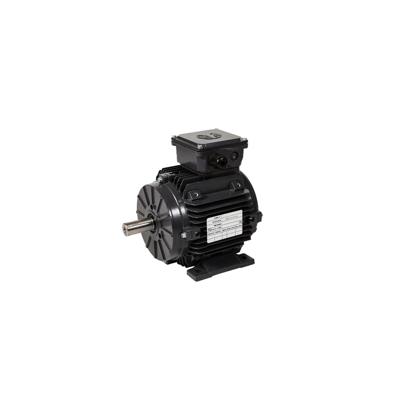
The decoupled approach splits the system into two distinct physical locations. You place the motor inside the application space. You place the inverter or VFD remotely inside a separate, climate-controlled electrical cabinet. This architecture relies on an AC induction motor, a permanent magnet motor, or a raw BLDC motor.
When should you specify this architecture? Engineers use decoupled systems heavily in legacy building retrofits. They also mandate them for ultra-high horsepower applications. Extreme environmental conditions almost always require decoupled electronics.
Let us examine the implementation pros. Thermal and environmental isolation solves many engineering headaches. You protect delicate variable-frequency drives from harsh operational zones. By moving the drive to an electrical room, you shield it from abrasive dust, corrosive moisture, and extreme heat. Maintenance flexibility provides another distinct advantage. You isolate your failures. If the remote drive suffers a fault, you simply replace the drive. If the motor bearings fail, you replace the motor. You do not discard perfectly good components. Finally, you gain scalability. A single, large external inverter can sometimes control multiple identical motors simultaneously. You synchronize an entire fan wall from one control point.
The implementation cons require careful engineering oversight. Installation complexity rises dramatically. You must allocate significant physical wall space for NEMA-rated control cabinets. You must run complex, specialized wiring between the cabinet and the application space. A qualified technician must manually tune the VFD parameters to match the motor nameplate data.
Harmonic distortion risks also emerge. Long cable runs between an external inverter and a motor act like capacitors. They amplify electrical noise. They generate common mode voltage. This voltage seeks ground through the motor shaft. It causes electrical arcing inside the physical bearings. We call this electrical discharge machining (EDM). Over time, EDM creates microscopic pits on the bearing races. The bearings become noisy and eventually seize. You must install specific mitigation hardware. Line reactors, dV/dt filters, and specialized shielded cables are mandatory.
Best Practice: Keep VFD-to-motor cable runs as short as physically possible to minimize capacitive coupling and harmonic wave reflection.
Common Mistake: Running VFD output cables in the same conduit as standard power cables, resulting in severe induced noise.
Let us provide a strict side-by-side evaluation lens for procurement and engineering teams. You must weigh these technical parameters against your site constraints.
The comparison chart below highlights the core differences between the two architectures.
| Evaluation Criteria | Integrated Setup | Decoupled Setup |
|---|---|---|
| Physical Footprint | Zero external cabinet space required. | Requires dedicated wall or panel space. |
| Thermal Tolerance | Low to Moderate. Electronics share motor heat. | High. Electronics reside in climate-controlled areas. |
| Installation Complexity | Minimal. Plug-and-play wiring. | High. Requires shielded cables and field tuning. |
| Bearing Protection | Internal grounding handles capacitive currents. | Requires external dV/dt filters and shaft grounding. |
Let us detail the specific evaluation factors:
Before finalizing any system, you must assess your baseline infrastructure. Are you retrofitting an existing building, or are you designing a new Original Equipment Manufacturer (OEM) product?
New designs strongly favor integrated EC motors. Engineers want maximum efficiency using minimal parts. Heavy industrial retrofits often favor external VFDs. Building operators prefer utilizing existing electrical room infrastructure while simply swapping out the mechanical fans.
You must prioritize risk mitigation regarding harmonics and power quality. Both inverter types rely on pulse width modulation (PWM). PWM introduces harmonic distortion back into your facility's power grid. They alter the perfect electrical sine wave. When rectifiers convert alternating current to direct current, they pull power in non-linear gulps. This erratic power draw pushes harmonic currents back upstream.
These currents multiply at different frequencies. We measure this as Total Harmonic Distortion (THDi). High THDi overheats facility transformers. It causes unpredictable behavior in sensitive IT servers sharing the same electrical grid. An integrated unit usually incorporates passive filtering chokes internally. They manage their own low-level noise. However, large decoupled systems require massive external line reactors.
You must specify active or passive harmonic filters regardless of your choice. Industrial facilities must meet strict IEEE 519 compliance standards for power quality. Failure to mitigate harmonics leads to overheated transformers, nuisance breaker tripping, and flickering lights.
Execute these next-step actions to secure a robust system:
An EC motor inherently utilizes an electronic inverter to function. The core engineering decision relies purely on physical location. You choose an inverter integrated directly into the motor housing, or you mount an external drive in a separate cabinet.
Choose integrated setups for compact, highly efficient, commercial-grade applications. They streamline installation and guarantee peak performance tuning. Opt for external inverter architectures when environmental hazards, extreme thermal loads, or heavy industrial requirements dictate physical separation. Evaluate your spatial constraints, audit your thermal environment, and prioritize long-term maintenance accessibility to select the perfect architecture.
A: No. An Electronically Commutated motor relies on an inverter to convert the AC supply to DC and pulse the internal electromagnets. Without this electronic switching, the motor cannot generate a rotating magnetic field. It will not function.
A: Integrated units act as a single assembly. If the electronic board fails, you generally replace the entire motor unit. Decoupled systems provide modularity. You can swap a failed AC motor or a failed external VFD independently. This changes your facility maintenance strategy.
A: Yes. Upgrading to an integrated EC motor represents a highly common retrofit. It achieves immediate efficiency gains through variable speed control. It often requires fewer structural changes to your electrical cabinets than installing a completely new external VFD system.
