


Views: 0 Author: Site Editor Publish Time: 2026-08-26 Origin: Site


Investing in high-efficiency Electronically Commutated (EC) motors is a widespread procurement priority. Buyers often secure excellent motors but fail to match aerodynamic characteristics of the EC fan impeller to physical system constraints. This critical oversight directly neutralizes potential energy savings.
The EC motor provides superior electrical efficiency and precise variable speed control. However, the physical fan impeller determines actual volumetric flow, static pressure capability, and acoustic output. Without accurate aerodynamic matching, the best motor simply works harder to overcome poor fluid dynamics.
Our objective is to give engineers and system designers a strict, evidence-based selection framework. You will learn how to accurately evaluate and specify impeller designs. We base this methodology on operating points, spatial limits, and strict noise restrictions. You can dramatically improve system longevity by following these guidelines.
The energy savings of an EC motor are effectively neutralized if the impeller geometry does not match the system's impedance curve.
Backward-curved impellers offer peak aerodynamic efficiency for high-pressure systems, while forward-curved designs prioritize high airflow in space-constrained footprints.
Micro-tolerances matter: clearance gaps between the impeller and the inlet ring (gap flow) can cause non-trivial efficiency losses in real-world implementations.
Specifying an EC fan impeller requires balancing three competing variables: operating pressure, acoustic limitations (blade pass frequency), and physical dimension restrictions.
Often, procurement teams see an IE4 or IE5 motor rating and consider the efficiency problem solved. They assume high-efficiency electrical components guarantee a high-efficiency mechanical system. They completely ignore critical aerodynamic losses happening just millimeters away from the motor shaft. This creates a false sense of optimization.
The reality involves complex fluid dynamics. The physical fan impeller acts as the sole translation point between rotational mechanical torque and directed fluid motion. It converts the motor's energy into measurable airflow. Poor selection forces the system to operate outside its peak aerodynamic efficiency curve. When this happens, airflow encounters unnecessary internal resistance. Consequently, the EC motor draws significantly more electrical power just to meet baseline volumetric targets. It essentially fights against its own aerodynamic mismatch, generating excess heat instead of useful airflow.
A successful deployment demands a holistic engineering approach. You must actively pair the motor's highly precise, variable-speed capabilities with a customized aerodynamic profile. You must design or select the impeller specifically for the application’s expected static pressure and airflow demands. Engineers evaluate success not by motor nameplate data, but by measuring actual watts consumed per CFM delivered in the field.
Selecting the correct aerodynamic profile defines the ultimate capability of your ventilation equipment. Three primary structural categories dominate the commercial and industrial markets. Each category brings highly specific fluid mechanic strengths and inevitable operational trade-offs.
These sophisticated designs feature blades curving away from the direction of wheel rotation. They provide the highest peak aerodynamic efficiency available in the market today. This specific geometry creates a unique, self-limiting power consumption curve. It inherently prevents motor overload regardless of unexpected system pressure fluctuations or sudden drops in resistance. We typically specify them in high static pressure applications. For example, data center Computer Room Air Conditioning (CRAC) units, massive air handling units (AHUs), and HEPA-filtered cleanroom ceilings rely heavily on them.
The primary trade-off involves physical packaging. A backward-curved EC fan impeller requires a significantly larger housing footprint and wheel diameter to achieve the same total airflow as competing designs.
Forward-curved blades point aggressively toward the direction of rotation. They act almost like a scoop, catching and throwing the air. They excel at moving massive air volumes at much lower operating rotational speeds. This characteristic makes them incredibly compact. They are the ideal choice for incredibly tight HVAC enclosures, residential furnaces, and low-profile fan coil units.
However, they deliver substantially lower overall aerodynamic efficiency. They also carry a severe risk of motor overload if system resistance drops unexpectedly. You must monitor their operating environment closely to prevent failures.
These heavy-duty blades radiate straight outward from the central hub, much like spokes on a wagon wheel. Engineers specify them almost exclusively for high-pressure, harsh industrial environments. They handle heavy dust, wood chips, and severe particulate loading exceptionally well because they resist material buildup.
Despite this extreme ruggedness, they remain entirely uncommon in standard commercial settings. Their aggressive, chopping aerodynamic action creates extreme acoustic profiles. The resulting noise levels make them completely unsuitable for quiet indoor environments or noise-restricted urban spaces.
Impeller Category Comparison
Impeller Type | Blade Profile | Key Strength | Primary Trade-Off |
|---|---|---|---|
Backward-Curved | Curves away from rotation | Highest efficiency; self-limiting power | Requires a larger physical footprint |
Forward-Curved | Curves toward rotation | Compact; moves high volumes at low speeds | Lower efficiency; potential motor overload risk |
Radial/Straight | Straight out from the hub | Excels in harsh dust and particulate handling | Highly disruptive acoustic noise profile |
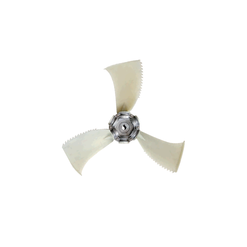
Geometry dictates fluid behavior. You cannot accurately assess an impeller by glancing at generic marketing efficiency numbers. You must critically evaluate specific physical features and their direct fluid dynamic outcomes.
A fundamental rule of thumb governs basic blade dimensions. Wider blades push significantly more air mass at a given RPM. However, they demand substantially more motor torque, impacting motor sizing and heat generation. Alternatively, blade count directly influences the acoustic signature. The exact number of blades dictates the "blade pass frequency" (BPF). This mathematical frequency determines the prominent tonal noise profile of the equipment. Modifying blade count allows acoustic engineers to shift irritating noise into less noticeable frequency bands, avoiding structural resonance.
Many budget-focused applications utilize flat, stamped sheet metal blades. While cheap to produce, they cause chaotic airflow. Advanced engineering designs utilize complex, 3D-profiled airfoil shapes similar to airplane wings. Airfoil blades actively reduce unwanted air turbulence. They prevent boundary layer separation—a phenomenon where air detaches from the blade surface, causing massive drag. This smooth fluid dynamic directly improves acoustic performance. It also substantially lowers energy consumption compared to basic flat designs, yielding faster efficiency returns.
Material choice heavily impacts long-term longevity and rotational efficiency. Consider your environment carefully:
Fiberglass-Reinforced Composites: Modern polymers significantly reduce rotational mass. Lighter mass improves motor bearing life by reducing gyroscopic forces. Injection molding also allows manufacturers to create highly complex, optimized 3D aerodynamic shapes. Metal stamping simply cannot achieve these exact curves.
Aluminum and Steel Castings: Metals inherently increase rotational weight. However, extreme operating environments strictly require them. Highly abrasive industrial air streams, continuous high-temperature exhausts, or environments requiring explosion-proof construction mandate robust metal fabrication.
Theoretical efficiency curves plotted in pristine laboratory environments often fail dramatically in the field. Laboratory testing assumes perfectly uniform, laminar air entry. Real-world installations introduce chaotic variables and physical obstructions causing aerodynamic failures.
Micro-tolerances create macro problems. A physical clearance gap must exist between the stationary inlet cone and the rapidly rotating EC fan impeller. Large or uneven clearances allow high-pressure discharge air to bleed backward into the low-pressure inlet zone. This creates intense internal recirculation vortices. We categorize this as the gap flow penalty. It silently destroys aerodynamic efficiency, forcing the motor to spin faster just to compensate for recirculating, wasted air.
Lab-tested aerodynamic efficiency drops rapidly during physical installation. Poor manufacturing tolerances or sloppy assembly often cause an immediate 3% to 5% efficiency loss. Sometimes the penalty is much more severe. If the surrounding system enclosure disrupts laminar inflow, the fan struggles to capture air evenly. Uneven turbulence at the inlet face ruins intended pressure generation. This causes uneven loading on the fan bearings and drastically reduces component lifespan.
Never evaluate performance in an isolated vacuum. A fan behaves very differently inside an actual, cramped HVAC cabinet. Proximity to dense cooling coils alters the airflow trajectory. Thick HEPA filters increase static resistance abruptly. Sharp, sudden ductwork transitions near the fan discharge severely degrade the expected velocity profile. The Air Movement and Control Association (AMCA) widely documents these "System Effect Factors." You must account for these predictable pressure drops during the initial specification phase, or your system will definitively underperform.
Common Mistake: Placing an impeller directly against a sharp 90-degree duct bend. Always provide at least one full fan diameter of unobstructed straight ductwork at the discharge to allow pressure recovery.
Selecting the optimal unit demands rigorous, methodical shortlisting logic. Follow these exact sequential steps to specify the proper aerodynamic unit for your specific system architecture.
Plot the System Resistance Curve: Never specify a fan based on a single data point. You must mathematically map the required CFM (Cubic Feet per Minute) against your expected static pressure across all operating states. This parabolic line forms your system resistance curve. It dictates exactly how much pressure the air needs to overcome internal friction.
Match the Operating Point Strategically: Ensure your application's required operating point falls squarely in the peak high-efficiency zone of the specific impeller’s published performance curve. Do not place the operating point at the extreme left (surge region) or extreme right (choke region) margins. Margin operation causes fluid instability, severe vibration, and eventual motor burnout.
Overlay Acoustic Constraints: Sound propagation matters heavily in commercial spaces. Review the sound power level data strictly at your specific operating RPM and pressure. A fan impeller might appear incredibly quiet at half speed during a test, but it could become deafening at its peak necessary operating point.
Next Action: The next crucial step involves demanding better engineering data. Do not rely on generalized marketing claims, broad brochures, or single-number efficiency metrics. Request highly detailed fan curves from the manufacturer. Ask for granular acoustic data sheets tailored specifically to your exact intended operating conditions.
An EC motor only provides the raw electrical potential for systemic efficiency. Ultimately, the precise physical geometry of the EC fan impeller dictates the physical reality of your volumetric output and acoustic performance. Neglecting fluid dynamics in favor of simple motor specifications wastes expensive electrical potential.
Achieving true, measurable optimization requires a deeply holistic system evaluation. You must carefully match aerodynamic profiles, acoustic limits, and dimensional constraints to your exact field operating point. You must proactively consider gap flow tolerances and real-world system effect factors before finalizing any enclosure design.
Stop guessing with generic performance curves failing to reflect your installation realities. Contact specialized technical sales engineering teams today. Request custom fan curve modeling, review exact sound spectrum data, and leverage application-specific selection tools to secure the perfect aerodynamic fit for your next demanding project.
A: No. While a better impeller improves aerodynamics, the core electrical efficiency and variable-speed capabilities require an integrated EC motor and controller.
A: Steeper blade angles generally move more air per revolution but generate higher turbulence and noise. Optimized 3D sweeping blade designs help mitigate this trade-off.
A: Not universally. While backward-curved offers better energy efficiency and is ideal for high-pressure systems, forward-curved impellers are necessary when high volume is required within a very restricted spatial footprint.
