


Views: 0 Author: Site Editor Publish Time: 2026-08-30 Origin: Site


Operating a compliant cleanroom requires balancing strict air change rates with escalating energy costs and thermal load management. Facility managers constantly seek reliable methods to maintain pressure cascades without overextending operational budgets. The transition from traditional AC motors to Electronically Commutated (EC) technology in Fan Filter Units (FFUs) is no longer just an energy-saving initiative; it is a critical baseline for modern cleanroom facility management. This shift redefines how you control environmental parameters at the micro-level.
For buyers at the decision stage, evaluating an EC fan for FFU applications requires moving beyond basic spec sheets. You must analyze system-wide integration, operational cost savings, and implementation risks. We will explore the critical performance metrics, network compatibility constraints, and practical deployment strategies you need to master. By understanding these variables, you can confidently navigate vendor selection and ensure a highly efficient, future-proof cleanroom infrastructure.
EC fans reduce FFU energy consumption by 30–50% compared to AC motors, significantly lowering operational OPEX.
Integrating a fan filter unit EC fan allows for precise, localized airflow adjustments via centralized BMS (Modbus/BACnet), eliminating manual damper tuning.
Reduced motor heat output directly decreases the secondary load on cleanroom HVAC cooling systems.
Successful deployment requires rigorous upfront planning regarding harmonic distortion, network topology for control systems, and specific grid dimension compatibility (e.g., standard 2x4 systems).
Traditional AC fans run at fixed speeds. They force facility teams to rely on manual damper adjustments to regulate airflow. These mechanical adjustments waste significant energy. They also fail to adapt to filter loading over time. As HEPA or ULPA filters accumulate particles, static pressure increases. An AC fan cannot autonomously push harder against this resistance, which leads to degraded airflow and potential compliance failures.
EC motors provide a highly engineered alternative. They utilize built-in microprocessors to convert incoming AC power to DC internally. This internal conversion allows for continuous, variable speed control. Instead of running at full capacity and choking the output mechanically, the motor only uses the exact electrical draw required to meet your setpoint. They respond dynamically to changing environmental conditions.
Upgrading requires higher upfront capital expenditure (CAPEX). However, you quickly offset this initial investment. Facilities benefit from reduced electrical consumption immediately. You also see substantially lower cooling loads because EC motors generate much less waste heat. Furthermore, optimized airflow extends HEPA and ULPA filter life. Expected payback periods typically range from 1.5 to 3 years. By focusing on these concrete operational savings, you build a compelling justification for facility upgrades.
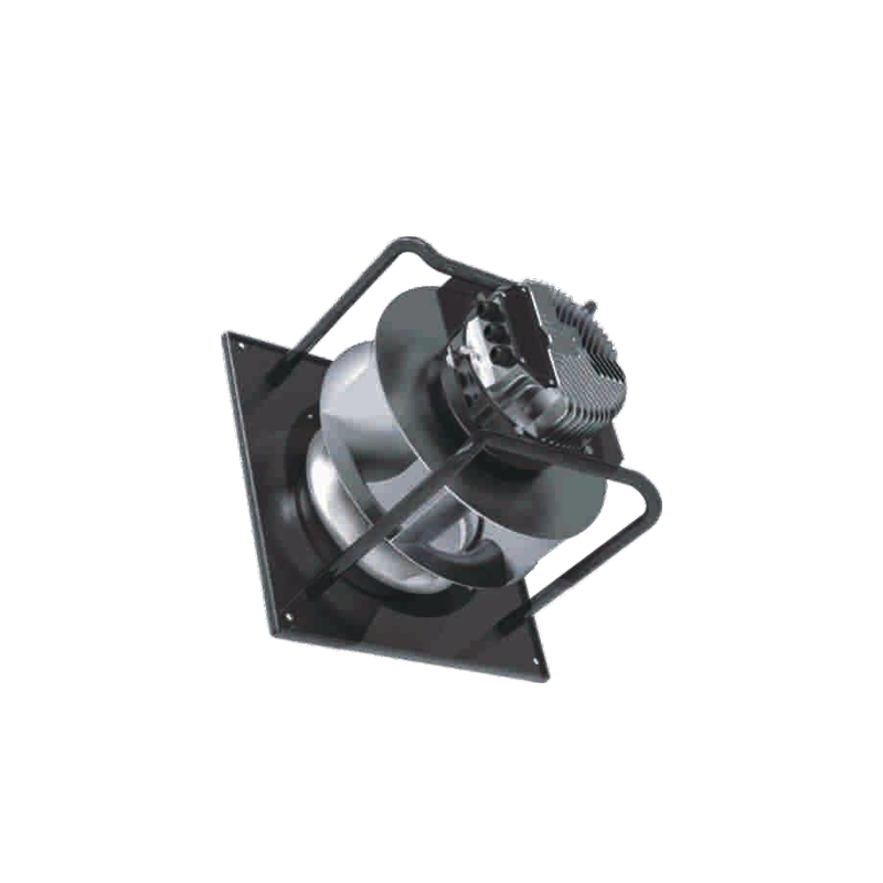
Not all EC motors perform equally in critical environments. You must scrutinize specific performance data to ensure the hardware meets ISO certification requirements. Relying on generalized marketing claims often leads to undersized equipment or excessive acoustic disruptions.
You must evaluate CFM (Cubic Feet per Minute) delivery against Watts consumed across various static pressure points. Cleanrooms are dynamic environments. As filters clog, resistance rises. Assess the fan's ability to maintain constant airflow autonomously. High-quality controllers feature constant volume algorithms. They sense the pressure drop and automatically ramp up RPMs to deliver the exact required CFM without manual intervention.
When selecting a fan filter unit EC fan, always demand performance curves mapped specifically to your facility's target pressure drops. Never rely on free-air performance metrics, as they do not reflect real-world filter resistance.
Acoustic performance is critical, especially in ISO Class 1-5 environments where large arrays of FFUs operate simultaneously. Verify sound pressure levels (dBA) at your required operating speeds.
Look for aerodynamically optimized impellers. Backward-curved centrifugal impellers generally minimize turbulence. They move air efficiently while keeping the noise profile low. A poorly designed impeller will generate low-frequency hums that cause operator fatigue and interfere with sensitive vibration-isolated equipment.
Every watt consumed by a fan motor eventually turns into heat. You must calculate the exact heat dissipation of the EC motor into the cleanroom supply air. Because EC technology operates efficiently, they emit far less thermal energy than AC variants. You must quantify this reduction accurately to size your secondary HVAC cooling requirements correctly. Oversizing the main chiller plant leads to wasted capital and inefficient cooling cycles.
Performance Comparison Overview
Performance Metric | Legacy AC Motor FFU | Modern EC Motor FFU |
|---|---|---|
Speed Control | Fixed speed; requires manual dampers | Variable speed; programmable via BMS |
Energy Efficiency | Low (high electrical waste) | High (30-50% energy reduction) |
Thermal Output | High heat dissipation | Low heat dissipation |
Acoustic Profile | Higher turbulence and vibration | Optimized, quieter operation |
Filter Life Extension | Poor (static output) | Excellent (dynamic adjustment) |
Physical integration often presents hidden challenges during facility upgrades. A fan might boast excellent electrical specs, but if it fails to align with your existing ceiling infrastructure, project timelines will suffer.
Verify dimensional tolerances for standard cleanroom ceiling grids. In North America, standard 2x4 systems dominate the landscape, while 4x4 systems appear in larger, less compartmentalized cleanrooms. The housing must fit perfectly within the T-grid without forcing structural modifications. Even a millimeter of variance can compromise the structural integrity and the airtight seal of the cleanroom ceiling.
Assess the footprint and weight of the units for FFU replacements in existing facilities. EC units sometimes carry different weight distributions due to the integrated electronics. Ensure your current ceiling grid can support the suspended load.
Identify electrical infrastructure readiness early. You can often reuse existing AC wiring to deliver power to the new units. However, control wiring requires entirely new low-voltage networking. Planning the physical routing for these communication cables is essential to prevent messy, non-compliant overhead installations.
Ensure the fan housing creates a zero-bypass seal with the specified HEPA or ULPA filters. Any leakage around the filter gasket instantly degrades the ISO cleanliness rating. Pay close attention to the clamping mechanisms and gasket materials used by the manufacturer. They must withstand prolonged compression without degrading.
The true value of modern motorized impellers lies in their digital connectivity. Without proper networking, you leave significant operational advantages on the table.
Require native support for open protocols like Modbus RTU or BACnet. This ensures vendor-agnostic integration with your existing Building Management Systems (BMS). Proprietary control systems lock you into a single vendor for future upgrades and maintenance. Open protocols give you the freedom to integrate multiple facility subsystems into a single, cohesive dashboard.
Evaluate the daisy-chaining capacity of the fan controllers. Cleanrooms often utilize hundreds or thousands of individual filter units. Can the system reliably manage and monitor thousands of units from a single dashboard? Network latency and signal degradation become real issues in massive arrays.
Consider the following hierarchy for robust network scalability:
Device Level: Individual controllers mounted on each motor.
Gateway Level: Routers that aggregate data from groups of 50-100 units.
Supervisory Level: The central BMS server processing facility-wide metrics.
Look for software capabilities that allow for zone-based setback modes. You can program the BMS to reduce airflow during unoccupied hours, saving massive amounts of energy. The system must execute these setback commands without compromising cleanroom pressurization. It requires precise synchronization across multiple zones so that positive pressure always pushes air outward from the cleanest critical zones to lower-grade areas.
Deploying advanced ventilation technology introduces specific electrical and operational risks. You must anticipate these challenges during the design phase to prevent costly commissioning delays.
EC motors convert AC to DC using internal rectifiers. This non-linear load can introduce Total Harmonic Distortion (THD) into the facility's electrical grid. High THD overheats transformers, trips circuit breakers, and interferes with sensitive analytical equipment.
To mitigate this, always specify fans equipped with active or passive PFC (Power Factor Correction) filters. These filters smooth out the electrical draw, keeping the power grid stable. Do not assume PFC is standard; verify it within the manufacturer's technical documentation.
Networked equipment requires tight alignment between Information Technology (IT) and Operational Technology (OT) teams. Plan thoroughly for addressing, grouping, and software commissioning phases during deployment.
IP Addressing: Assign logical addresses to each unit based on physical location.
Grouping: Group units logically by cleanroom suite or pressure zone.
Testing: Perform point-to-point verification to ensure the BMS reads the correct data from the correct physical unit.
Verify vendor capacity and replacement parts availability. Because these motors utilize specific microelectronics, they remain subject to global supply chain fluctuations. A delayed shipment of critical control boards can derail a facility opening. Request detailed lead time estimates and ask vendors about their domestic warehousing strategies for spare parts.
Selecting a partner requires a methodical approach. Move past basic brochures and demand verifiable engineering data.
Request third-party certified performance curves. AMCA (Air Movement and Control Association) certification provides an independent guarantee that the fan will perform exactly as advertised. Avoid manufacturers who only supply in-house testing data.
Demand verifiable case studies demonstrating precise energy savings and operational cost reductions in similar ISO-rated environments. You want proof that their equipment sustains long-term efficiency under continuous commercial loads. Look for examples showing baseline power draws compared to post-installation metrics.
Before full-scale procurement, run a field test. Install a small array of 5 to 10 units in a non-critical zone. Use this pilot program to field-test BMS integration, verify actual noise levels, and measure real-world power draw under local facility conditions. This pilot phase reveals network blind spots and mechanical mating issues before you commit to a multi-million-dollar rollout.
Once you validate the pilot, proceed to issue a highly detailed Request for Proposal (RFP). Include exact static pressure requirements, grid sizing constraints, and required control topologies. Specify your THD limits and demand documented proof of open-protocol compatibility.
Selecting the right hardware for your overhead infrastructure is a strategic operational decision. It requires balancing upfront costs with long-term efficiency, compliance, and precise environmental control. By moving away from fixed-speed legacy systems, facilities unlock dynamic airflow management, reduce thermal burdens, and drastically lower energy consumption.
Rely on empirical performance data and rigorous integration testing rather than generic manufacturer claims. Ensure your engineering teams plan carefully for network scalability and electrical harmonics. Execute a well-monitored pilot test to validate network communication and aerodynamic performance. By strictly enforcing these evaluation standards, you ensure the chosen solution meets the uncompromising demands of your critical environment.
A: Lifespan is generally determined by the L10 bearing life. For high-quality units, this typically ranges from 40,000 to 70,000 hours of continuous operation. Actual longevity depends heavily on the running speed, ambient temperature, and adherence to routine maintenance schedules.
A: Yes, but it requires careful planning. You will face physical dimensional challenges, as the newer motors may have a different footprint or depth. Additionally, while you can reuse power lines, you must route new low-voltage control wiring to support Modbus or BACnet communications.
A: They can, but reputable manufacturers design them to meet strict CE and FCC compliance standards for EMI/RFI. Proper installation is critical. You must ensure correct grounding and use shielded communication cables to prevent any interference with sensitive metrology or manufacturing equipment.
A: Advanced controllers feature integrated algorithms and pressure sensors. As the HEPA filter accumulates particles and static pressure rises, the controller detects the restricted airflow. It automatically increases the motor's RPM to maintain a constant CFM output, ensuring continuous compliance.
