


Views: 0 Author: Site Editor Publish Time: 2026-09-03 Origin: Site


Data center thermal management accounts for up to 40% of total facility energy consumption. This massive electrical draw forces operators to constantly evaluate their Power Usage Effectiveness (PUE). Traditional alternating current (AC) fans operate at rigid, fixed speeds. They cannot efficiently adapt to dynamic IT loads. This operational rigidity leads to severe energy waste and unnecessary overcooling. Upgrading to an EC fan for data center environments fundamentally changes this dynamic. It transitions facilities from reactive cooling models to continuous, modulated thermal management. We wrote this guide to provide facility managers and engineers with an evidence-based framework. You will learn how to evaluate equipment upgrades accurately. We will help you calculate realistic returns on investment. Finally, we will share practical strategies to mitigate deployment risks during live facility retrofits.
Many older facilities still rely on legacy AC centrifugal and axial fans. These outdated units depend on mechanical dampers or external Variable Frequency Drives (VFDs) to reduce airflow. Mechanical dampers create heavy physical resistance. They force motors to work hard just to block the air they produce. Inefficient VFDs introduce harmful harmonic losses into your power grid. Both methods waste valuable electricity and degrade system reliability.
To justify an upgrade, operators need clear success criteria. You should look for several measurable improvements. First, demand a measurable reduction in mechanical PUE across your cooling infrastructure. Second, expect the elimination of localized server hotspots through highly targeted airflow. Finally, require a noticeable reduction in total harmonic distortion (THD) affecting your power distribution.
We must apply a skeptical lens here. Yes, modern airflow technology delivers superior performance. However, actual energy savings vary widely. They depend heavily on your current baseline efficiency. Local utility costs also play a major role in your financial outcomes. Furthermore, your facility must actually utilize variable speed control to see real benefits. If operators lock new fans at 100% speed constantly, you lose the primary advantage entirely.
Electronically commutated motors utilize highly efficient direct drive mechanics. They combine a brushless DC motor with integrated control electronics in one housing. This compact design completely eliminates external belt friction losses. It also enables smooth, step-less speed control from zero to 100 percent. You can precisely dial in the exact cubic feet per minute (CFM) required for specific server racks.
Seamless integration makes this hardware truly shine in enterprise environments. Standard control interfaces easily connect to your existing Building Management Systems (BMS). Common protocols include 0-10V, PWM, Modbus, and BACnet. These connections allow a data center cooling fan to adjust speeds instantly. They respond automatically to real-time server inlet temperature sensors. This creates a closed-loop thermal management system.
We also notice a significant secondary benefit during daily operation. These advanced motors operate much more quietly than legacy AC models. The reduced aerodynamic noise at lower RPMs drastically improves the occupational environment. On-site technicians experience less auditory fatigue while working inside the white space. Better acoustics lead to safer, more focused maintenance work on critical IT hardware.
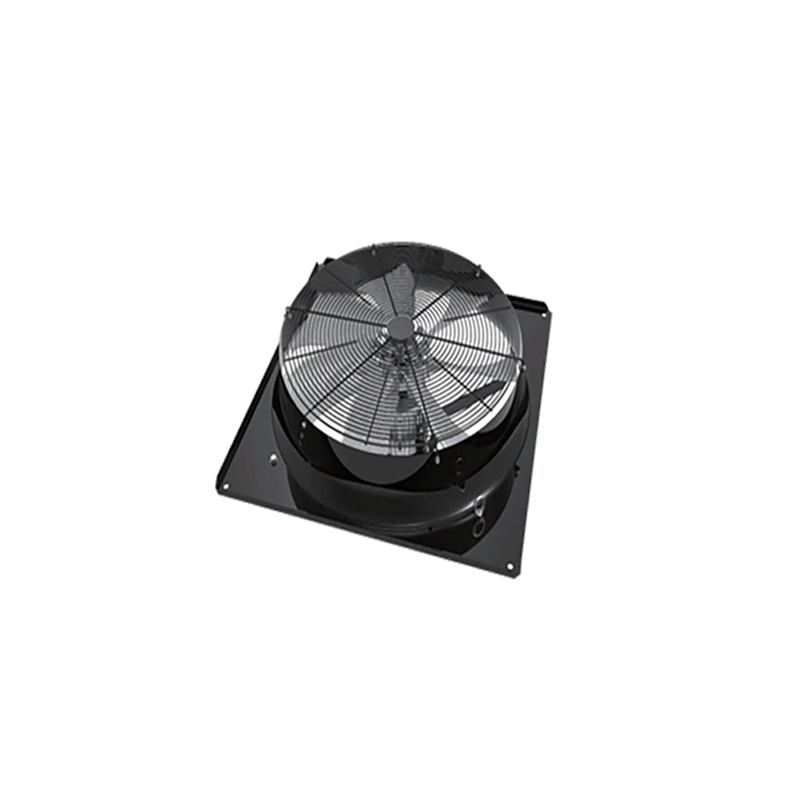
Let us look directly at motor efficiency numbers. Traditional AC permanent split capacitor (PSC) motors max out around 60 to 70 percent peak efficiency. Their efficiency curves drop sharply when operated below maximum speed. Advanced EC motors push that boundary up to 85 or 92 percent. More importantly, they maintain this high efficiency even when running at half capacity.
Table 1: Motor Efficiency and Performance Comparison
| Motor Type | Peak Efficiency | Partial Load Efficiency | Speed Control Method | Maintenance Requirements |
|---|---|---|---|---|
| Standard AC (PSC) | 60% - 70% | Drops significantly below 80% | Mechanical dampers / VFDs | High (Belt replacement, greasing) |
| EC (Brushless DC) | 85% - 92% | Remains above 80% at low speeds | Integrated electronic modulation | Low (Sealed bearings, direct drive) |
The real magic happens when we apply the affinity laws. The Cube Law of fluid dynamics states power consumption varies with the cube of fan speed. If you reduce fan speed by just 20 percent, you cut power consumption by nearly 50 percent. This mathematical reality provides a massive advantage for dynamic IT loads. Running fans slightly slower yields exponential energy savings.
Calculating your return on investment requires transparent inputs. You must account for several distinct financial variables:
Do not assume every facility sees the exact same payback period. You must crunch the numbers using your local baseline utility rates. Facilities running 24/7 usually see faster payback cycles.
Facility managers generally choose between two primary deployment architectures. Direct 1-to-1 retrofits utilize large plug fans. These units drop directly into existing Computer Room Air Handler (CRAH) or Computer Room Air Conditioning (CRAC) chassis. They are perfect for replacing end-of-life blowers quickly. You keep the existing sheet metal enclosure intact.
Alternatively, you can deploy full modular fan arrays. Many professionals call these fan walls. This modular approach changes how you distribute air entirely. Arrays stack multiple smaller fans into a single unified grid. This structural shift offers massive operational advantages over single large blowers.
First, arrays provide inherent N+1 or N+2 redundancy. If one small fan fails, the BMS detects the pressure drop instantly. The remaining fans automatically ramp up their RPMs. They maintain the required static pressure and CFM seamlessly. Your servers never experience a thermal event during a single motor failure.
Second, they optimize your physical footprint inside the facility. Array structures often require significantly less cabinet depth than massive legacy centrifugal fans. You can recover valuable floor space. Finally, arrays deliver highly uniform airflow. Multiple smaller impellers push air evenly across the entire cooling coil surface. This uniform velocity profile dramatically improves overall heat exchange efficiency.
Every facility manager fears the cutover phase. Swapping mechanical components in a live, mission-critical environment introduces serious risk. You absolutely cannot compromise server inlet temperatures during the upgrade process. A sudden loss of pressure can cause IT equipment to overheat in minutes. Planning the physical swap requires extreme attention to detail.
We highly recommend phased rollouts to mitigate this operational danger. Retrofit only one CRAH unit at a time. You might also deploy temporary cold aisle containment during the process. Heavy plastic curtains and blanking panels restrict air spillage. This strategy ensures adjacent operating units can carry the thermal load while technicians work.
You must evaluate space and structural limitations beforehand. Technicians need adequate existing plenum space to maneuver bulky equipment safely. Always check doorway and elevator clearances to ensure new assemblies fit through the corridors. Additionally, verify dynamic weight distribution limits on your raised floors. Fan walls distribute weight differently than single heavy blowers.
Electrical compliance deserves special engineering attention. Your existing infrastructure must handle the specific electrical profile of the new equipment. Many large arrays require active power factor correction built into the design. Consult your electrical engineer early. You must prevent tripping main breakers upon initial system startup.
Specifying new hardware requires careful technical analysis. You must start with accurate performance matching. Engineers need to read and map specific fan curves comparing CFM against static pressure. The new equipment must meet or exceed the legacy equipment's worst-case scenario output. Do not guess on air pressure drops across deep server cabinets.
Next, verify component reliability metrics rigorously. Look closely at the stated L10 bearing life specifications. This number tells you how long the bearings will last under continuous load. Check the IP ratings to ensure adequate dust and moisture protection. Demand standard UL and CE certifications for all electronic components to ensure fire safety compliance.
Vendor support and supply chain strength matter just as much as hardware specs. Evaluate the manufacturer's ability to provide localized technical support. Can they assist your team with complex BMS commissioning? Do they stock readily available replacement parts in your region? A great motor fails eventually; quick replacement parts prevent extended disasters.
For next-step actions, we suggest a cautious, measured approach. Initiate a pilot retrofit on a single, non-critical CRAC unit first. Validate your estimated power measurements physically using sub-metering. Prove the engineering concept definitively before committing capital to a facility-wide rollout.
Upgrading cooling infrastructure is not merely a basic component swap. It represents a strategic shift toward intelligent, demand-based thermal management. While the initial capital expenditure requires solid justification, the operational benefits speak for themselves. You move away from rigid, wasteful airflow toward highly responsive systems.
The powerful combination of energy savings, mechanical redundancy, and precise BMS integration is undeniable. It makes modern variable-speed technology the clear standard for updating legacy server rooms. You gain peace of mind knowing the system handles variable loads automatically.
We encourage you to take practical action today. Request an independent energy audit for your facility. Contact a specialized cooling engineer to model specific CRAH retrofit scenarios for your building. Let them measure your current airflow and calculate your projected payback periods accurately.
A: Depending on utility rates, duty cycles, and local energy rebates, the typical payback period ranges from 18 to 36 months.
A: Yes, EC plug fans are specifically designed to be backward-compatible with legacy unit dimensions, often replacing older belt-driven centrifugal fans.
A: No, EC fans have integrated electronics for commutation and speed control, eliminating the need for external VFDs and avoiding associated harmonic distortion issues.
A: EC fans are direct-drive and use sealed bearings, eliminating the need for belt replacements, tensioning, and regular motor greasing required by traditional AC belt-driven fans.
