


Views: 0 Author: Site Editor Publish Time: 2026-08-30 Origin: Site


Upgrading legacy belt-driven or standard AC fans to electronically commutated (EC) technology is a primary lever for reducing HVAC energy consumption. It helps facility managers meet tightening regulatory baselines, such as DOE energy standards. You cannot simply swap components and hope for immediate success. While the efficiency gains are well-documented, executing a successful upgrade requires navigating strict spatial constraints. You must also manage controls integration and calculate upfront capital requirements accurately. It demands a strategic approach to guarantee long-term reliability for your building. This guide provides a functional framework for facility managers and engineers. We help you evaluate, justify, and implement an EC motor upgrade without unexpected downtime or cost overruns. You will learn how to assess system readiness, choose the correct architectural layout, and build a resilient financial model for your ventilation project.
Before committing capital to an EC fan retrofit, you must determine if the existing system truly warrants an upgrade. An objective assessment prevents unnecessary spending on units that might require full replacement soon anyway.
A well-documented readiness assessment ensures stakeholder alignment. It bridges the gap between engineering requirements and corporate financial expectations. By auditing the existing baseline first, you lay a secure foundation for subsequent design decisions.
Once you justify the upgrade, you must select the physical layout of the new equipment. Facility engineers typically choose between two primary architectural paths. Each path solves specific mechanical problems.
This approach involves swapping a single legacy motor and fan assembly for a single EC equivalent. Mechanics remove the old belt-driven centrifugal blower and install a similarly sized direct-drive unit.
This architecture is best for smaller AHUs and specific exhaust applications. You commonly see this in bathroom ventilation or multifamily residential buildings. It suits projects dealing with tight budgets and limited physical access.
However, this method carries distinct limitations. It retains the single-point-of-failure risk inherent in the original design. If the new fan fails, the entire zone loses airflow. Furthermore, a single fan may not resolve existing dead spots in large plenums, leading to uneven coil face velocities.
Instead of a massive single fan, this mechanism uses a matrix of smaller, parallel-operating EC fans. Installers build a structural grid inside the AHU casing to hold multiple compact units.
This layout is best for critical infrastructure. Data centers, hospitals, and large-scale industrial ventilation systems require high redundancy. If one fan drops offline, the remaining fans ramp up to maintain the required static pressure and CFM.
The advantages are substantial. You achieve zero operational downtime during individual fan failure. Installers find it much easier to transport these smaller components through standard facility doors and elevators. Additionally, arrays provide a highly uniform airflow distribution across cooling coils, significantly improving heat transfer efficiency.
Retrofit Architecture Comparison
| Feature | 1-to-1 Direct Replacement | EC Fan Array (Fan Grid) |
|---|---|---|
| Redundancy | None (Single point of failure) | High (N+1 capability) |
| Installation Access | Requires large clearances for heavy parts | Easily fits through standard doors |
| Airflow Profile | Concentrated, prone to dead spots | Uniform across the entire plenum |
| Initial Capital Cost | Generally lower | Higher (due to multiple motors/structure) |
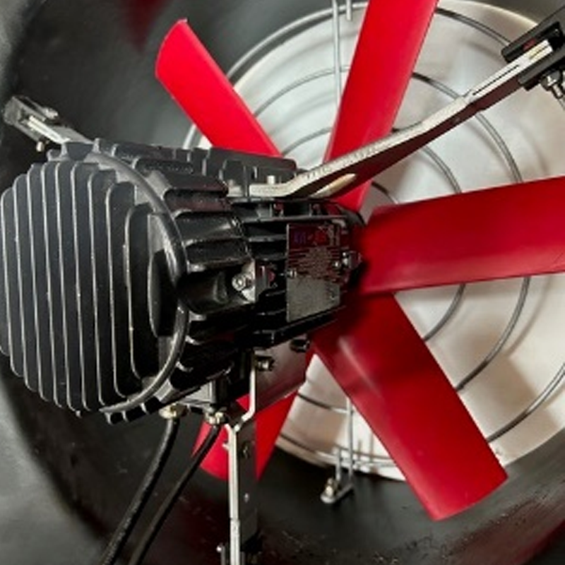
Selecting the proper hardware requires strict technical vetting. You cannot rely solely on basic horsepower matches when specifying equipment. A successful integration hinges on aerodynamics, control compatibility, and physical fit.
Aerodynamic Matching: You must verify that the proposed fan can meet or exceed the existing system's performance. Evaluate both static pressure and CFM requirements at optimal RPMs. Old belt-driven fans often operated outside their ideal efficiency curves. Mapping the new fan curve against real-world ductwork resistance prevents underperformance. Ask your vendor for detailed selection software outputs.
BMS Integration and Protocols: Assess your facility's control compatibility early. Determine if the new equipment supports native 0-10V or PWM analog inputs. Most modern systems require Modbus or BACnet integration for remote monitoring. An Industrial EC Motor usually includes built-in communication cards. This eliminates the need for separate external VFD panels but requires precise low-voltage wiring. Ensure your controls contractor understands these native interfaces.
Form Factor and Retrofit Kits: Evaluate the availability of modular bulkhead plates. You need custom mounting hardware to prevent bypass air inside the existing AHU casing. If air leaks around the fan panel, efficiency plummets. Proper kits also isolate vibration. They prevent the new high-speed impellers from rattling older sheet metal enclosures.
Environmental Ratings: Check the specific operating environment. Ensure the selected motor has the appropriate Ingress Protection (IP) rating. High-humidity environments, coastal areas, or industrial exhaust streams demand heavy corrosion resistance. Specifying an IP54 or IP55 rating protects the integrated electronics from dust and moisture intrusion, ensuring a long operational life.
Theoretical designs often clash with real-world building conditions. You must plan the physical execution meticulously to avoid costly delays. Protect your facility by following structured implementation steps.
Ignoring these execution steps often leads to erratic operation. Carefully managing the physical tear-down and rebuild ensures the new technology performs as engineered.
Securing project funding requires a transparent, accurate financial model. You must demonstrate clear value to building owners and financial officers. Emphasize operational efficiency and maintenance reductions over the equipment's lifespan.
Calculating Operational Savings: Factor in energy reduction as your primary financial driver. However, do not stop there. You must also calculate the complete elimination of routine mechanical upkeep. Legacy systems demand regular belt replacements, bearing greasing, and external VFD troubleshooting. The new direct-drive technology removes these recurring labor and parts expenses entirely. Track these historically to build a stronger justification for the initial capital outlay.
Navigating Utility Rebates: Outline the specific process for securing regional utility incentives. Many utility programs heavily subsidize these efficiency upgrades. Note that most energy providers require strict pre-approval. You usually must conduct baseline energy logging *before* the retrofit begins. If you tear out the old fan before logging its power draw, you will likely forfeit your rebate money. Engage your local utility representative during the early design phase.
Payback Modeling: Transparently define the break-even point for the project. In most commercial applications, you see a return on investment within 2 to 5 years. Acknowledge openly that the initial capital expenditure is higher than a simple like-for-like repair. Show how the long-term energy drop and maintenance elimination offset this initial premium rapidly. Presenting realistic, conservative models builds trust with financial decision-makers.
An upgraded ventilation system is a high-yield infrastructure investment when engineered correctly. It shifts maintenance-heavy, inefficient mechanical setups to smart, variable-speed operation. You gain precise environmental control while drastically cutting utility demand. Success relies entirely on careful planning, accurate airflow measurement, and rigorous commissioning protocols.
When selecting partners, prioritize vendors or contractors who provide comprehensive support. Look for teams that offer pre-installation site audits, custom airflow mapping, and turnkey commissioning. Avoid contractors who treat this as a simple parts-swap. The built-in electronics require a sophisticated understanding of both aerodynamics and building management systems.
We recommend scheduling a facility energy audit immediately. Consider running a pilot installation on a single problematic AHU. This pilot acts as a proof of concept. It allows you to prove localized performance and financial returns before committing to a costly, facility-wide rollout.
A: It varies from a few hours for a simple rooftop unit exhaust to several days for a complex, multi-fan array in a large commercial AHU. Pre-fabrication of mounting plates significantly reduces onsite downtime. Planning your staging areas and demolition paths beforehand also accelerates the overall installation timeline.
A: No. EC motors have integrated commutation and speed control electronics. Existing VFDs must be bypassed or removed entirely during the retrofit. Feeding a synthetic AC waveform from an old VFD into the integrated electronics will cause severe damage and immediately void manufacturer warranties.
A: Frequently, yes. Because they exceed standard efficiency baselines, many utility programs offer custom or prescriptive rebates. These are often calculated per horsepower or per projected kWh saved. You must usually perform baseline energy logging and gain pre-approval before beginning demolition to secure these funds.
A: When properly sized and maintained, high-quality units typically operate for 40,000 to 70,000 hours. The lifespan is largely limited by the physical durability of the motor bearings. Keeping the electronics cool and ensuring the AHU environment remains within acceptable humidity limits will maximize operational longevity.
