


Views: 0 Author: Site Editor Publish Time: 2026-07-24 Origin: Site


Data centers face a massive operational challenge today. Artificial intelligence and high-performance computing push rack power densities to extreme levels. Facilities must rapidly cool these intense loads while meeting stringent Power Usage Effectiveness (PUE) mandates. The EC axial fan provides the mandatory baseline for modern cooling efficiency. Electronically commutated technology inherently reduces energy consumption compared to legacy options. However, engineers cannot simply install any unit. Improper selection often leads to destructive resonance failure, inadequate static pressure, or severe integration bottlenecks. This guide delivers a practical, engineering-focused framework. You will learn how to evaluate and shortlist the right equipment for your specific environment. We will explore implementation strategies for enterprise and hyperscale facilities. Our focus remains strictly on maximizing aerodynamic performance and ensuring zero compromise on system uptime.
Modern data centers demand precise thermal management frameworks. Facilities must align cooling requirements with ASHRAE TC 9.9 guidelines. These guidelines establish strict thermal envelopes for data processing environments. Compliance ensures hardware longevity and prevents localized overheating. Engineers must calculate specific cooling loads based on peak rack densities. You cannot rely on historical cooling assumptions.
Legacy alternating current and direct current systems introduce significant operational friction. They suffer from poor partial-load efficiency. They also require complex secondary wiring for variable speed control. These outdated systems drain power unnecessarily. Modern electronically commutated units eliminate these operational hurdles entirely. They deliver precise airflow matching without external variable frequency drives.
Evaluating capacity begins with determining the required cubic feet per minute (CFM). You must calculate the exact CFM needed to extract peak heat loads. However, capacity alone cannot guarantee uptime. Mission-critical Tier III and Tier IV facilities demand strict redundancy protocols. Engineers must integrate N+1 or N+2 redundancy into the initial design phase. This approach ensures continuous operation even during individual component failures.
System Capacity and Redundancy Benchmarks
| Facility Tier | Cooling Redundancy Minimum | Operational Focus |
|---|---|---|
| Tier I / II | N (No redundancy) | Basic capacity matching |
| Tier III | N+1 | Concurrent maintainability |
| Tier IV | N+2 or 2N | Fault tolerance under live load |
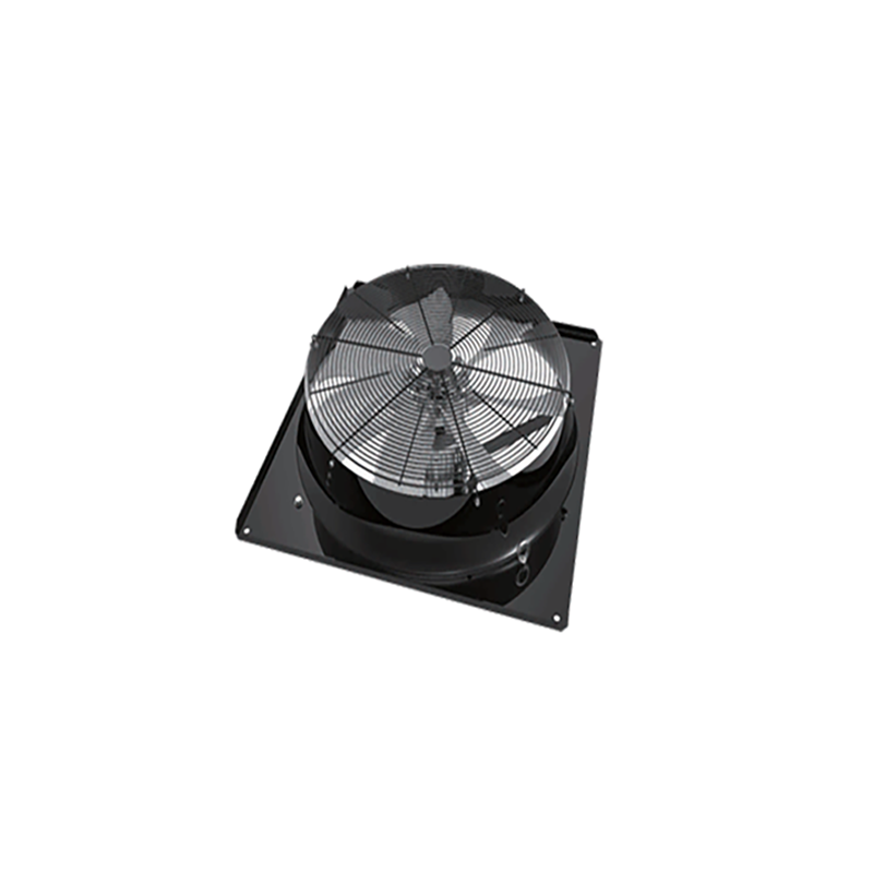
Evaluating fan performance requires a deep understanding of aerodynamic principles. You must know how to read and interpret fan curves accurately. High-density server racks create substantial internal backpressure. This backpressure constantly resists cooling airflow. The selected unit must maintain nominal airflow at elevated static pressure points. If pressure exceeds capability, the unit enters an aerodynamic stall region. Stall conditions destroy efficiency and drastically reduce airflow delivery.
Motor efficiency separates premium units from baseline commodities. Electronically commutated motors integrate intelligent control electronics directly into the housing. Look for motors delivering greater than 80% efficiency across various loads. Data center precision cooling systems operate at partial loads nearly 90% of the time. High partial-load efficiency ensures massive energy reductions over the equipment lifecycle.
Telemetry protocols govern how the cooling infrastructure communicates. A reliable data center cooling fan must provide seamless control integration. Evaluate the onboard intelligence carefully. The system should connect easily to Building Management Systems (BMS) or Data Center Infrastructure Management (DCIM) software. Standard protocols like Modbus RTU, RS485, and 0-10V/PWM signals remain industry standards. These connections enable real-time speed adjustments and immediate failure reporting.
Acoustic profile management addresses serious occupational hazards inside data halls. High-velocity air movement generates intense tonal noise. Engineers must evaluate specific impeller blade designs to control decibel output. Manufacturers utilize serrated trailing edges to break up sound waves. They also deploy specialized biometric blade geometries. These features mitigate disruptive tonal noise effectively. Crucially, they accomplish this acoustic reduction without sacrificing volumetric airflow.
Physical constraints dictate equipment selection directly. Server rack exhaust systems operate under severe dimensional limitations. Solutions for 1U, 2U, and 3U server chassis require highly specialized designs. These tight spaces feature extreme airflow impedance due to densely packed internal components. Fans must operate at exceptionally high revolutions per minute (RPM) to overcome this resistance. Engineers prioritize high static pressure generation over sheer diameter in these applications.
Computer Room Air Conditioning (CRAC) and Air Handling (CRAH) units follow different operational rules. These large-scale systems generally pressurize raised floors across entire data halls. They rely on larger diameter units to move massive air volumes. Evaluation here focuses on maximizing volumetric flow rates. You must prioritize sustained energy efficiency during constant, high-volume operation. Slower-spinning, large-diameter blades deliver better efficiency for raised floor pressurization.
Modern data centers rapidly shift toward parallel configurations. Fan walls and arrays replace massive single-unit blowers. These arrays offer compelling engineering advantages. They create uniform airflow distribution across heat exchangers. Arrays also provide immediate internal redundancy. If one unit fails, the others automatically adjust speed to compensate. You can run multiple fans at lower, highly efficient speeds. This method drastically outperforms running a single massive blower at maximum load.
Parallel Configuration Benefits
Deploying advanced active components introduces hidden electrical risks. Harmonic distortion presents a major threat to facility infrastructure. Total Harmonic Distortion of Current (THDi) degrades power quality significantly. Switched-mode electronics inside these motors create non-linear electrical loads. You must specify units equipped with active or passive Power Factor Correction (PFC). Proper PFC prevents dirty power from flowing back into the facility UPS system. Clean power distribution ensures uninterrupted facility operation.
Parallel arrays introduce complex mechanical risks. Multiple fans operating at identical speeds generate sympathetic vibrations. This phenomenon creates destructive structural resonance. Engineers must implement specific countermeasures to protect the equipment framework.
Resonance Mitigation Strategies
Maintenance accessibility serves as a primary evaluation metric. Enterprise facilities cannot tolerate cooling downtime for routine repairs. You must evaluate modular array designs rigorously. Hot-swappability determines long-term maintenance success. Technicians should easily replace a single failed unit under live load conditions. They must complete this swap without initiating a full system shutdown. Quality array systems do not require specialized calibration after a single component replacement.
Selecting the right manufacturing partner dictates long-term project success. You must evaluate vendors based on their distinct supply chain capabilities. Many facilities require highly customized integration features. Assess the vendor’s ability to deliver specialized wire harnesses matching your exact control panels. Physical environment protection also matters deeply. High-humidity environments or direct liquid cooling deployments require specific IP ratings. Always specify IP54 or IP55 certification for harsh data center zones. Furthermore, comprehensive global warranty support ensures rapid parts replacement across international facility locations.
Engineers must demand rigorous empirical data before approving any hardware. Never accept theoretical performance numbers for mission-critical cooling. Require AMCA (Air Movement and Control Association) certified performance curves. These independent certifications validate airflow and static pressure claims accurately. Additionally, investigate the documented Mean Time Between Failures (MTBF). Ask for empirical MTBF data recorded under your expected thermal loads. Real-world validation separates reliable infrastructure components from unproven commodities.
Selecting an electronically commutated unit represents a strategic infrastructure decision. It is never a simple commodity purchase. Your choices directly impact operational reliability and environmental compliance. Prioritizing intelligent control integration ensures seamless facility management. Accurate static pressure matching prevents destructive aerodynamic stalls. Physical redundancy within arrays protects system uptime against sudden mechanical failures. Engineers should audit their current cooling footprints immediately. We recommend consulting technical specialists to model custom parallel arrays tailored to your precise thermal loads.
A: Practical lifespan depends primarily on bearing longevity. High-quality units typically deliver 40,000 to 60,000 hours of Mean Time Between Failures (MTBF) operating at 40°C. Continuous operation at maximum speed degrades bearing grease faster. Running units at lower, variable speeds significantly extends operational life.
A: Yes, retrofitting is highly practical. However, engineers must strictly verify physical dimensional constraints first. You must also bypass existing Variable Frequency Drives (VFDs) and legacy contactors. This modification allows the new internal controller to manage speed natively, ensuring proper telemetry integration.
A: These units leverage the affinity laws of aerodynamics, often called the cube law. Reducing fan speed by just 20% drops power consumption by nearly 50%. Native onboard electronics constantly optimize these speeds to match exact heat loads, drastically lowering overall facility energy usage.
