


Views: 0 Author: Site Editor Publish Time: 2026-08-23 Origin: Site


Electronically Commutated (EC) fans offer superior energy efficiency and inherently quieter motor operation compared to traditional AC alternatives. However, real-world acoustic performance varies heavily based on specification and integration. HVAC engineers, OEM product designers, and facility managers often face a complex engineering challenge. Evaluating these airflow systems requires analyzing mechanical geometry, electrical commutation, and systemic airflow dynamics comprehensively.
We designed this guide to provide a highly technical, objective framework. It helps identify the physical and electrical variables influencing your baseline EC fan noise level. Specifiers can use these insights to evaluate system specifications accurately. Our goal is to help you choose the optimal low noise ventilation fan for your precise application without falling for exaggerated marketing claims. By understanding these interactions, you can prototype quieter, more reliable systems.
Size and Speed Correlation: Larger fans running at lower RPMs generally move the same air volume with significantly less broadband noise than smaller, high-RPM fans.
Motor Commutation Matters: Advanced continuous control algorithms in EC motors minimize the electromagnetic and electrical "hum" often found in traditional systems.
System Resistance is Critical: The highest quality EC fan will still generate excessive acoustic noise if forced to operate against high static pressure or within poorly optimized aerodynamic enclosures.
Bearing Selection Dictates Lifespan Noise: Dual ball bearings offer longevity but may present a different acoustic profile over time compared to sleeve or fluid dynamic bearings.
Noise increases exponentially as fan speed rises. Aerodynamic acoustic output strictly follows the fifth power law of fan speed. Doubling the rotational speed does not simply double the noise. It increases the sound power level by roughly 15 decibels. This dramatic jump makes high-speed operation acoustically hostile in sensitive environments.
Upsizing the fan diameter to reduce operational RPM remains the most reliable strategy. A larger impeller moves a massive volume of air at slow speeds. This approach achieves the required cubic feet per minute (CFM) while keeping decibels low. For engineers seeking a low noise ventilation fan, always maximize the physical envelope. Specifying a 250mm unit at 1,500 RPM always sounds quieter than forcing a 120mm unit to spin at 4,000 RPM.
Standard straight-blade designs often struggle to control trailing edge turbulence. As air slips off a flat blade, it creates chaotic microscopic vortices. These vortices generate a loud broadband "rushing" sound. Modern aerodynamic profiles address this physical limitation directly.
Advanced impellers utilize optimized, swept, or serrated blade shapes. A serrated edge breaks up trailing edge turbulence into smaller, less audible frequencies. Furthermore, the number of blades and their pitch angle dictate specific acoustic signatures.
Tonal Noise: Generated by the blade passing frequency (BPF). Fewer blades typically create distinct, annoying low-frequency tones.
Broadband Noise: Created by general air turbulence. Multi-blade swept designs spread the acoustic energy across a wider spectrum, sounding like smooth white noise.
The mechanical friction inside the motor housing heavily influences perceived acoustics over time. Designers must select bearings based on specific operational lifespans and temperature environments.
Sleeve Bearings: These operate very quietly upon initial installation. A lubricant film separates the shaft from the bearing. However, they are highly prone to rapid wear in high-temperature environments. Once the lubricant dries out, mechanical grinding noise increases aggressively.
Dual Ball Bearings: These produce a slightly higher initial mechanical noise due to metal ball friction. However, they maintain highly stable acoustic profiles over a 50,000+ hour lifespan. They resist extreme temperatures and varied mounting angles without degrading.
Evaluate your trade-off carefully. Use sleeve bearings for intermittent cooling needs where absolute silence is required immediately. Rely on dual ball bearings for continuous, 24/7 industrial operation where acoustic stability matters most.
Traditional AC induction motors rely on alternating current intersecting stator coils to induce rotation. This creates magnetic slip and a continuous line-frequency humming. Depending on your geographic region, you will hear a distinct 50Hz or 60Hz rumble echoing through the chassis.
EC motors inherently resolve this issue. They operate as brushless DC motors utilizing onboard AC-to-DC conversion. The integrated electronics convert incoming grid power into direct current. The controller then intelligently pulses the coils. This completely removes magnetic slip noise. The resulting rotation feels substantially smoother, eliminating the heavy line-frequency humming entirely.
While EC technology removes low-frequency hum, it can introduce high-frequency electrical whining. The internal controller regulates speed by rapidly switching voltage on and off using Pulse Width Modulation (PWM). The frequency of this switching directly impacts your overall EC fan noise level.
If the PWM switching frequency falls between 20Hz and 20kHz, it intersects with audible human hearing ranges. The motor coils physically vibrate at this exact frequency, emitting a piercing electronic whine.
To evaluate a fan properly, inspect the internal driver circuit specifications. Look for EC controllers utilizing switching frequencies optimized well above the 20kHz threshold. Operating at 25kHz or 30kHz pushes the electrical whining into the ultrasonic range. The motor becomes perceptually silent to human operators.
Electrical switching does not just generate airborne noise. Unshielded electronics emit significant Electromagnetic Interference (EMI). High-voltage pulses create localized magnetic fields around the stator coils.
In sensitive equipment enclosures, this unshielded electrical noise translates into physical vibration. The fluctuating magnetic fields can induce structural resonance in nearby metallic panels. Medical devices, server racks, and high-density PCB cooling applications are particularly vulnerable. Shielded cables and properly grounded motor housings prevent these magnetic fields from escaping. Proper EMI mitigation stops electrical noise from becoming mechanical resonance.
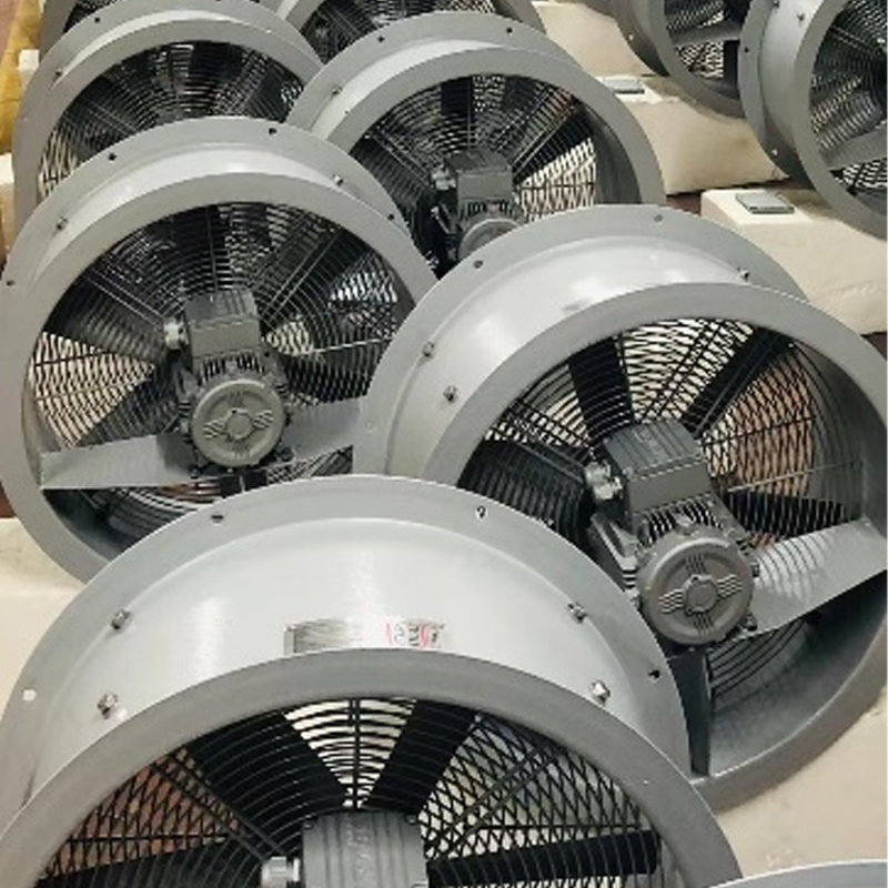
A high-quality motor and aerodynamic impeller mean nothing if the system integration is flawed. Every fan features a specific performance curve mapping airflow against static pressure. Operating an EC fan outside of its peak efficiency point creates severe acoustic penalties.
When you force a fan to push air against unusually high static pressure, the blades lose grip on the air. The airflow detaches from the blade surface. This creates an aerodynamic stall. Stall induces heavy turbulence, low-frequency buffeting, and erratic vibration. Always match the fan's peak efficiency window to your system's actual operating pressure. Moving leftward on the performance curve invariably raises the decibel output.
The immediate environment surrounding the impeller dictates how air enters and exits the chassis. Placing components too close to the intake or exhaust violently disrupts laminar flow. Common offenders include densely packed heat sinks, sharp finger guards, and thick HEPA filters.
Obstructions placed immediately against the fan face chop the airstream. This chopping action causes vortex shedding, resulting in a loud siren-like whining. Use a practical rule of thumb to prevent this problem. Maintain a clearance distance equal to at least half the fan's diameter on the intake side. Smooth, unobstructed intake paths prevent structural resonance and keep the acoustic profile low.
Acoustic engineers differentiate between airborne aerodynamic noise and structure-borne noise. Airborne noise travels directly through the air to your ears. Structure-borne noise travels through solid materials. If you mount a motor rigidly to a thin sheet metal chassis, the entire cabinet acts as a giant acoustic amplifier.
You must break the mechanical transmission path to stop structure-borne noise. Implement decoupled mounting systems during assembly.
Insert soft rubber grommets around mounting screws.
Apply foam gasket seals between the fan frame and the metal housing.
Use specialized anti-vibration mounts for heavy industrial units.
Isolating the physical frame guarantees that natural motor vibrations dissipate before they can excite the surrounding enclosure.
Engineers often take dB(A) ratings on spec sheets at face value. This is a common and critical mistake. Acoustic testing methodologies vary wildly between manufacturers. You must understand the difference between sound power and sound pressure to compare units accurately.
Sound power (Lw) measures the absolute acoustic energy emitted by the source. It remains constant regardless of the environment. Sound pressure (Lp) measures the acoustic waves hitting a specific point in space. Sound pressure changes based on testing distance and room reflections. A reading taken at 1 meter looks drastically different than one taken at 3 meters.
Acoustic Measurement Comparison
Metric | Definition | Environmental Dependency | Best Use Case |
|---|---|---|---|
Sound Power (Lw) | Total acoustic energy emitted by the fan. | Independent of distance or room setup. | Comparing absolute noise generation between different fan models. |
Sound Pressure (Lp) | Perceived noise level at a specific location. | Highly dependent on distance and room acoustics. | Evaluating operator exposure limits in a real-world space. |
Fixed-speed AC fans run at 100% output continuously. This wastes energy and maximizes acoustic disruption. The primary advantage of EC technology lies in proportional speed control. Manufacturers typically utilize 0-10V analog signals or high-frequency PWM inputs.
Success in acoustic engineering relies on leveraging this capability. A properly sized system designed to run at 60% capacity during typical loads will consistently outperform a fixed-speed system. By mapping the speed precisely to real-time cooling demands, you keep the normal operating decibels virtually silent. You only experience maximum acoustics during rare, peak thermal events.
Never rely on unverified marketing claims regarding decibel outputs. Manufacturers can easily manipulate testing environments to produce favorable numbers. Check the datasheets for strict ISO testing standards.
Standardized testing guarantees independently verifiable results. ISO 3744 and ISO 3745 define precise methodologies for measuring sound power levels in hemi-anechoic and fully anechoic chambers. These certifications ensure the manufacturer captured the data using calibrated microphones positioned at standardized geometric distances. When you compare two fans certified under ISO 3744, you can trust the baseline comparison.
Controlling your overall system acoustics is a systemic engineering task, not just a line-item purchasing decision. You cannot simply buy a quiet motor and expect a silent machine. Achieving optimal results requires addressing multiple physical disciplines simultaneously.
The most effective solutions perfectly balance physical dimensions, advanced electrical control, and systemic airflow design. Upsize your impellers to reduce rotational speed. Select internal drivers utilizing high-frequency PWM to eliminate electronic whine. Finally, maintain clear aerodynamic pathways to prevent turbulent vortex shedding.
We strongly recommend prototyping with multiple EC fan models under real-world static pressure conditions. Test the units inside your actual chassis, not just in free air. By evaluating performance across varying load profiles, you will successfully specify the ideal EC fan noise level parameters before finalizing large-scale procurement.
A: Yes, aerodynamic noise drops significantly with RPM reduction due to the fan laws. However, if electrical switching noise (PWM whine) or structural resonance is present at that specific lower speed, the perceived annoyance may remain. You must isolate both electrical and mechanical variables to ensure quiet operation at low speeds.
A: Spec sheet dB(A) ratings are tested in free-air, anechoic chambers without obstructions. Real-world installation introduces systemic backpressure, airflow turbulence from protective grilles, and structural vibrations passing into the chassis. These environmental factors significantly elevate the measurable decibels above the laboratory baseline.
A: Generally, yes. They are significantly quieter than AC fans due to the complete lack of magnetic slip and low-frequency line-voltage hum. Compared to standard DC fans, EC units often feature superior continuous control electronics and optimized stators. These upgrades yield lower vibration profiles at matching airflows.
