


Views: 0 Author: Site Editor Publish Time: 2026-08-20 Origin: Site


Specifying an industrial fan requires balancing two opposing forces. Engineers must deliver precise airflow while overcoming significant system resistance. You cannot afford to compromise on energy efficiency or acoustic performance in modern designs. Highly dense system architectures introduce complex impedance profiles. Pushing air through dense HEPA filters and tight heat sinks naturally creates immense resistance. This makes specifying the right equipment a critical task for overall system reliability.
Electronically Commutated (EC) technology now sets the standard for managing demanding pressure capabilities alongside variable speed control. This guide provides a practical framework for evaluating and shortlisting EC fans based on your specific system requirements. You will learn how to analyze performance curves, avoid aerodynamic stall, and navigate modern compliance standards seamlessly.
System Impedance Dictates Selection: Accurate calculation of pressure drops across filters, coils, and ductwork is the non-negotiable first step before evaluating any EC fan static pressure limits.
Curve Intersection is Critical: A successful specification relies on finding the precise operating point where the system impedance curve intersects the EC fan's performance curve at peak efficiency.
Design Variations Matter: Centrifugal EC fans (especially backward-curved) typically outperform axial designs in high-resistance applications, though modern high static pressure EC fans offer hybrid solutions.
Risk Mitigation: Operating too close to the fan curve's stall region introduces acoustic resonance, mechanical stress, and efficiency losses.
Modern ventilation and industrial cooling systems demand increasingly compact footprints. Engineers constantly face the challenge of packing more components into smaller spaces. Dense form factors inevitably create severe airflow restrictions. When you force air through thick HEPA filters, intricate server heat sinks, or complex ductwork, the system generates high resistance. We refer to this resistance as system impedance. Overcoming this impedance requires a fan capable of generating substantial push force.
Traditional AC motors struggle in these highly restrictive environments. They often suffer from motor slip and generate excess heat when pushed against high resistance. Here is where Electronically Commutated (EC) technology changes the paradigm. EC motors utilize an integrated electronic controller to manage brushless DC technology. They maintain optimal torque and high variable speed efficiency even when static pressure fluctuates. Unlike traditional designs, an EC motor continuously adjusts its speed to meet the exact load requirement. This dynamic adjustment prevents unnecessary energy waste.
The ultimate success criteria for any ventilation specification rely on three distinct metrics. First, you must achieve the target volumetric flow rate, typically measured in CFM or CMH. Second, you must overcome the total static pressure, measured in Pascals (Pa) or inches of water gauge (inH2O). Finally, you must achieve both parameters at the absolute lowest power consumption in Watts. Mastering this three-variable equation ensures your system avoids thermal failure while meeting stringent energy standards.
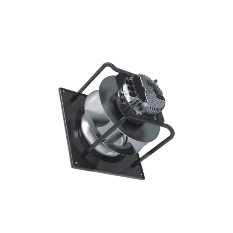
Selecting the correct impeller geometry is just as important as choosing the right motor technology. Different form factors handle system impedance in vastly different ways. Understanding these mechanical characteristics prevents costly specification errors down the line.
Axial fans move air parallel to the fan shaft. They represent the go-to solution for high airflow applications where resistance remains minimal.
Optimal Use Case: Engineers rely on axial fans for low-to-medium pressure environments. Common applications include agricultural ventilation, large heat exchangers, and open-air cooling systems.
Limitations: Axial designs inherently struggle against heavy resistance. When system impedance spikes unexpectedly, axial fans become highly prone to stalling. They simply lack the centrifugal force needed to push air through dense obstructions effectively.
When you encounter demanding system resistance, backward-curved centrifugal fans usually provide the most reliable solution. These units draw air in axially and exhaust it radially.
Optimal Use Case: This design serves as the industry standard for robust applications. It performs exceptionally well in precision air conditioning units, cleanrooms, and complex data center cooling arrays.
Advantages: Backward-curved impellers offer non-overloading power characteristics. The motor will not draw excessive current even if the airflow drops to zero. Peak efficiency naturally occurs right in the middle of the pressure curve. This makes it much easier to specify a high static pressure EC fan that operates efficiently under normal working conditions.
Forward-curved fans feature multiple shallow blades curved in the direction of rotation. They generate specific airflow characteristics suited for tight spaces.
Optimal Use Case: Use these fans when you face strict spatial constraints. They can deliver required pressure at significantly lower operating speeds (RPMs) compared to backward-curved models.
Trade-offs: Forward-curved fans suffer from narrower peak efficiency bands. If system resistance drops unexpectedly—such as someone removing a filter—the motor can quickly overload. Engineers must specify these fans carefully to avoid pushing the motor past its continuous operating limits.
You cannot specify a fan simply by reading its maximum airflow and maximum pressure values on a datasheet. Real-world performance relies entirely on how the fan interacts with your specific system impedance. You must analyze the EC fan static pressure curve to guarantee successful operation.
Every specification begins with a graph. The X-axis represents airflow, while the Y-axis represents static pressure. First, you calculate and plot your system impedance curve. Because pressure relates to the square of airflow, this curve sweeps upward parabolically. Next, you overlay the manufacturer’s fan performance curve. The exact intersection of these two lines dictates your true operating point. The fan will only operate at this specific intersection.
A common mistake is selecting a fan where the operating point falls near the extreme ends of the curve. Operating near "free air" (maximum airflow, zero pressure) wastes potential motor capacity. Operating near the "shut-off" point (maximum pressure, zero airflow) drastically reduces efficiency. Engineers must always target the middle third of the pressure curve. This central zone offers the highest aerodynamic efficiency, the lowest acoustic output, and the longest bearing lifespan.
Most centrifugal and axial fan curves feature a noticeable "dip" on the left side of the graph. We refer to this critical zone as the aerodynamic stall region.
Technical Risk: The stall point occurs when the impeller blades can no longer maintain smooth airflow. Boundary layer separation happens. At this point, static pressure suddenly drops even if the motor increases its RPM.
Consequence: Operating inside or near the stall region causes severe turbulence. You will experience massive spikes in low-frequency noise. The turbulent flow also induces severe mechanical vibrations, which accelerate bearing wear and ultimately cause premature fan failure.
Table 1: EC Fan Operating Zones and Characteristics
Operating Zone | Location on Curve | Aerodynamic Efficiency | Acoustic Profile | Recommended Action |
|---|---|---|---|---|
Free Air | Far Right (Max CFM) | Low | Moderate | Avoid for high impedance systems. |
Optimal Range | Middle Third | Maximum | Quiet / Stable | Target this zone for the operating point. |
Stall Dip | Upper Left | Extremely Low | Loud / Resonant | Never specify a fan to operate here. |
Shut-off | Far Left (Max Pa) | Zero | High Stress | Used only for laboratory baselines. |
Once you map the optimal operating point, you must evaluate external risk factors. Physical installation constraints and modern regulatory standards heavily influence final product selection.
Overcoming high resistance requires high impeller tip speeds. Higher speeds inevitably generate more noise. You cannot rely on "free air" acoustic baseline data provided in standard brochures. Always request sound power level (LwA) data measured exactly at your calculated operating point. Acoustic resonance can ruin an otherwise perfectly engineered ventilation system. Review specific frequency bands (octave bands) to ensure the fan noise will not conflict with the acoustic dampening materials used in your enclosure.
Global energy regulations continue to tighten. The European Union’s Energy-related Products (ErP) Directive mandates strict minimum efficiency levels. When dealing with substantial system impedance, overall fan efficiency often drops. You must verify that your chosen unit meets ErP 2015/2020 compliance standards. Look for high Fan Motor Efficiency Grades (FMEG). Specifying compliant EC fans ensures your end product remains legally viable for international markets.
Laboratory fan curves assume ideal airflow conditions. Real-world installations rarely offer such luxury. We call this discrepancy the "system effect." Placing a fan too close to an enclosure wall, a bulkhead, or a sharp duct bend disrupts intake air. This turbulence creates artificial static pressure not accounted for in your initial impedance calculations. Always ensure adequate plenum space around the fan inlet. If space constraints remain unavoidable, you must mathematically derate the fan’s performance curve to compensate for the system effect.
Moving from theoretical physics to practical procurement requires a structured approach. Use this framework to narrow down your supplier options effectively.
Before contacting any application engineering team, gather the following precise metrics:
Target Airflow: Define both the minimum required flow and the maximum allowable flow.
Calculated Static Pressure Drop: Determine the exact system resistance at your target maximum airflow.
Electrical Parameters: Note the available supply voltage, phase, and frequency.
Spatial Constraints: Document maximum allowable dimensions for the fan housing and impeller depth.
Not all manufacturer datasheets hold the same weight. You must demand absolute transparency regarding testing conditions. Ensure the supplier derives their performance curves using strict international testing standards. Look for references to AMCA 210 or ISO 5801. If a manufacturer tests fans without proper standardized protocols, their curve data will likely overstate real-world capabilities. Reliable data guarantees that your impedance calculations will hold up during physical prototyping.
Once you match your operating point to a reliable curve, transition out of theoretical analysis. Contact the manufacturer directly. Request 3D CAD models to check physical clearances within your assembly. Ask for detailed acoustic testing reports mapped to your specific RPM and pressure requirements. Finally, request lifecycle testing data (L10 bearing life expectancy) to validate long-term reliability under your calculated thermal and pressure loads.
Specifying an EC fan for heavy-duty resistance is an exacting exercise in matching system impedance with aerodynamic efficiency. You must accurately calculate your system’s pressure drop before looking at any manufacturer catalogs. Remember that over-specifying a fan leads to wasted space, excess noise, and unnecessary capital expenditure. Conversely, under-specifying guarantees thermal failure as the motor struggles to push air through dense obstructions.
Always map your operating point accurately to keep the fan in the middle third of its performance curve. Avoid the aerodynamic stall region at all costs to ensure long bearing life and quiet operation. Now that you understand the mechanics, compile your impedance calculations. Reach out to an application engineering team today to request custom curve modeling tailored strictly to your system architecture.
A: EC fans utilize an integrated closed-loop electronic controller to monitor and adjust motor behavior dynamically. Unlike AC motors that suffer from slip and speed loss under load, EC electronics maintain precise RPMs. By actively adjusting power input based on real-time resistance, they effortlessly sustain target airflow against fluctuating system impedance.
A: The definition depends on the specific application threshold. However, these units generally utilize backward-curved centrifugal impellers or highly aggressive pitch axial blades. They are specifically engineered to maintain optimal airflow against substantial resistance (measured in hundreds or thousands of Pascals / inH2O) without stalling or motor overloading.
A: Relying on variable speed to fix poor calculations carries significant risks. While an EC fan can increase its RPM to push past unexpected resistance, doing so exponentially increases noise levels. Furthermore, pushing the motor continuously at its maximum threshold accelerates bearing wear and reduces overall system efficiency.
