


Views: 0 Author: Site Editor Publish Time: 2026-08-23 Origin: Site


HVAC and cooling systems devour a massive portion of facility operating expenses today. In many industrial and commercial buildings, legacy air-moving equipment relentlessly drives up base-load electricity costs. Facility managers constantly face mounting pressure to shrink these bloated utility bills without sacrificing performance. Shifting toward Electronically Commutated (EC) technology offers a primary mechanism for aggressive cost reduction. You should view this transition not just as an environmental initiative, but as a critical financial strategy. This upgrade directly targets the heavy energy waste inherent in outdated motor designs.
This article provides a transparent, engineering-backed framework to evaluate system efficiency. We will show you how to accurately assess base metrics and calculate true return on investment. You will also learn how to confidently navigate the practical risks of physical retrofit implementations. By understanding the core mechanics, you can transform your HVAC infrastructure from a cost center into a model of operational efficiency.
Efficiency at partial loads: The primary driver of cost reduction is the EC motor's ability to maintain high efficiency at reduced speeds, leveraging the affinity laws of fluid dynamics.
Measurable ROI: Facilities upgrading to EC technology typically observe a payback period of 1 to 3 years, heavily dependent on local utility rates and operating duty cycles.
System-level benefits: Beyond direct energy savings, EC upgrades reduce secondary thermal loads and extend equipment lifecycles through lower operating temperatures and vibration.
Implementation readiness: Success requires careful assessment of existing Building Management Systems (BMS), physical footprint compatibility, and potential harmonic distortion.
Traditional HVAC setups rely heavily on outdated AC induction motors. These legacy systems operate with severe fixed-speed limitations. An AC motor inherently wants to run at its maximum designed speed. Facilities historically controlled airflow by installing mechanical dampers. Dampers simply block the air path to reduce volume. This creates massive static pressure resistance. The motor continues working at full capacity, burning maximum electricity, while the damper chokes the output.
Eventually, the industry adopted Variable Frequency Drives (VFDs) to modulate AC motor speeds. VFDs represented an improvement over mechanical dampers. However, they introduce their own inefficiencies. When a VFD slows down an AC motor, the motor's internal efficiency drops drastically.
AC induction motors suffer from inherent energy waste known as motor slip. The rotor always spins slightly slower than the rotating magnetic field of the stator. This slip causes friction and electrical resistance. These stator and rotor losses convert your paid electricity into unwanted heat. Instead of moving air, the motor essentially becomes a space heater. This heat transfers into the airstream or the mechanical room. Your cooling system must then work harder to remove the exact heat your inefficient motor just generated.
Upgrading legacy infrastructure requires clear, measurable goals. You must define what a successful modernization looks like before approving capital budgets. An optimal upgrade achieves several technical benchmarks simultaneously.
Verifiable kW reduction: You must measure a clear drop in electrical draw at the panel.
Maintained air volume: The new system must deliver the required CFM (Cubic Feet per Minute) or CMH (Cubic Meters per Hour).
Seamless control integration: The modernized fans must communicate flawlessly with your existing automation platforms.
Reduced ambient heat: You should observe lower operating temperatures directly at the motor housing.
If an upgrade fails to meet these criteria, it remains an incomplete solution. Proper planning ensures you eliminate the base-load waste driving up your operating expenses.
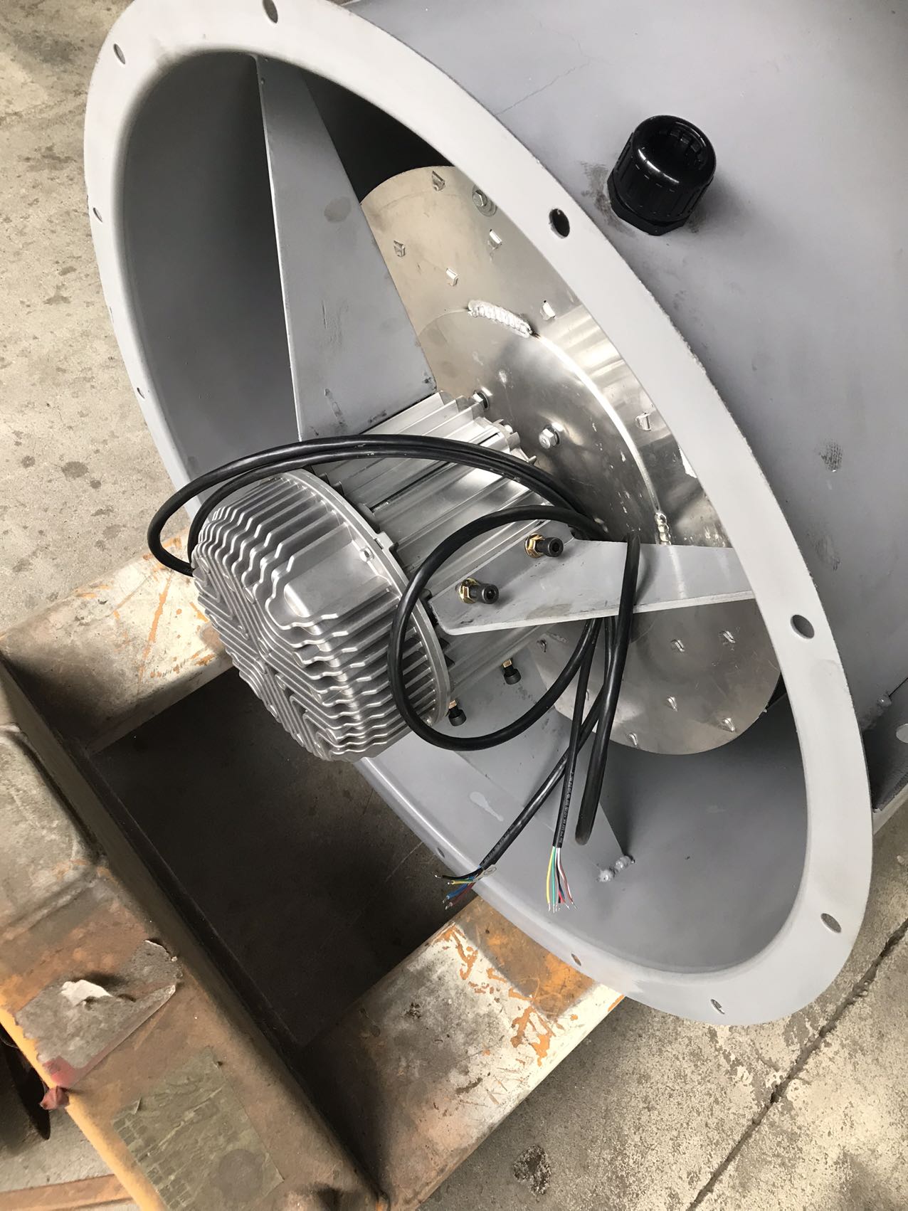
To reduce costs, we must understand the underlying technology. EC stands for Electronically Commutated. An EC motor is essentially a brushless DC motor. It features an integrated AC/DC converter and onboard electronics. You supply standard AC power to the unit. The internal electronics convert this to DC power. The motor then uses precise electronic commutation to spin the rotor. This eliminates the need for physical carbon brushes. It also removes the slip and heat losses inherent to AC induction designs.
The true financial magic happens at partial loads. Facilities rarely need their HVAC systems running at 100% capacity all day. Understanding how EC fan power consumption scales requires looking at the affinity laws of fluid dynamics. Specifically, we look at the cube law.
The power required by a fan varies with the cube of its speed. If you reduce the fan speed by just 20%, you do not save 20% on energy. You actually cut the power draw by nearly 50%. An EC motor capitalizes on this law perfectly. Because it lacks internal friction and slip, it modulates down smoothly. This exponential drop in power consumption yields massive daily savings for variable demand facilities.
Legacy AC motors look terrible on performance graphs. Their efficiency peaks in a very narrow band near full load. If you slow an AC motor down to 50% speed, its electrical efficiency plummets. It wastes a large percentage of its drawn power.
Conversely, EC technology boasts flat efficiency curves. An energy saving fan powered by an EC motor maintains 80% to 90% efficiency across a vast operational spectrum. Whether it runs at 30% speed or 90% speed, it uses electricity highly effectively.
Chart 1: Efficiency Curve Comparison
Operating Speed | Standard AC Motor Efficiency | EC Motor Efficiency |
|---|---|---|
100% (Full Load) | ~85% | ~90% |
80% Speed | ~70% | ~88% |
60% Speed | ~55% | ~85% |
40% Speed | ~40% | ~82% |
Best Practice: Always request manufacturer performance curves before purchasing. Compare the specific operational RPMs your facility requires against the motor's proven efficiency band.
Upgrading facility equipment requires a solid financial justification. You cannot rely on vague promises of "better efficiency." You need concrete math. Building a robust ROI framework allows you to forecast actual dollar savings accurately.
Estimating your direct electrical savings requires a straightforward formula. You need reliable data points from your current operations. Use the following sequential steps to build your projection.
Determine Baseline AC kW: Measure the actual power draw of your existing fan motors during typical operation. Do not just use the nameplate rating.
Determine Proposed EC kW: Consult the manufacturer data to find the expected power draw of the new unit at matching airflow volumes.
Calculate Annual Operating Hours: Track exactly how many hours the system runs per year. Continuous 24/7 operation equals 8,760 hours.
Apply Local Utility Rate: Find your blended electricity rate in dollars per kilowatt-hour ($/kWh), including peak demand charges.
The base formula is: (Baseline AC kW - Proposed EC kW) × Annual Operating Hours × Local Utility Rate = Annual Savings.
Direct energy savings only tell part of the story. You must factor in indirect savings to calculate true lifecycle cost reductions. EC fans inherently run cooler because they waste less energy as heat. Cooler operation drastically reduces wear on internal bearings.
Less bearing wear means an extended operational lifespan. Your maintenance team spends fewer hours lubricating parts, replacing belts, or swapping out burnt motors. Belt-driven AC fans require constant tension adjustments and belt replacements. EC fans are direct-drive units. They eliminate belt maintenance entirely. You reduce replacement part frequency and free up expensive labor hours for other facility needs.
You must practice transparency when presenting these ROI calculations to stakeholders. Note that maximum financial returns occur in continuous-duty applications. Data centers, commercial refrigeration, and large hospital HVAC systems see the fastest payback. These environments feature variable cooling loads operating 24/7.
Applications running at 100% speed continuously will still see savings. However, because they do not exploit the partial-load cube law, the payback period extends. Standby equipment that runs rarely might not justify the immediate capital upgrade. Focus your initial retrofit efforts on your heaviest base-load offenders.
Executing an upgrade requires navigating physical and electrical realities. Replacing old equipment with modern technology rarely involves a simple one-to-one swap. You must anticipate mechanical constraints and control integration challenges early in the planning phase.
Many legacy systems use massive centrifugal fans housed in large scroll casings. Swapping these out often involves installing EC plug fan arrays, commonly called fan walls. A fan wall uses multiple smaller EC fans working in parallel to deliver the same total airflow.
This approach offers incredible redundancy. If one fan fails, the others speed up to compensate. However, you must carefully address footprint changes. Multiple small fans alter the internal aerodynamics of the air handling unit (AHU). You must also evaluate structural weight. A fan wall often distributes weight differently across the AHU floor than a single massive motor. Ensure the existing flooring can handle the modified load distribution safely.
Your new hardware must communicate with your existing Building Management System (BMS). Failing to map this out causes significant commissioning delays. EC fans accept various control signals. You must determine what your current BMS outputs.
0-10V Analog: A traditional control method. Voltage scales directly with desired fan speed.
PWM (Pulse Width Modulation): A digital signal often used in smaller commercial setups.
Modbus RTU: A robust digital communication protocol. It allows the BMS to read exact RPM, power draw, and error codes directly from the fan.
Common Mistake: Do not assume your old analog BMS can read digital Modbus error codes natively. You may need signal converters or a BMS software update to unlock the fan's full diagnostic potential.
Solid-state electronics introduce unique electrical challenges. The internal AC/DC converters in EC motors draw current in non-linear pulses. This behavior can introduce harmonic distortion back into your facility's power grid.
High harmonic distortion degrades power quality. It can overheat transformers and cause sensitive electronics to malfunction. Acknowledge this risk during the design phase. High-quality fans include integrated active power factor correction (PFC). If you install large arrays, you may need passive or active harmonic filters at the distribution panel. Consult an electrical engineer to ensure your retrofit maintains pristine facility power quality.
The market offers numerous products claiming high efficiency. Selecting the right manufacturer ensures your investment performs as calculated. You need a rigorous evaluation process to separate marketing hype from engineering reality.
Do not accept generic efficiency claims. Demand specific fan curves tailored to your facility. Every air handling system operates against a specific static pressure. The fan must be selected to operate at its absolute peak efficiency point for your specific airflow requirements. If a vendor cannot provide a precise performance map matching your ductwork's impedance, find another supplier. The wrong fan size will hunt for the correct speed, wasting energy and stressing the bearings.
Table 1: Vendor Evaluation Checklist
Evaluation Category | Minimum Requirement | Why It Matters |
|---|---|---|
Data Transparency | Specific fan curves provided | Ensures operation at peak efficiency. |
Integration | Modbus RTU / 0-10V native support | Guarantees seamless BMS communication. |
Acoustics | Sound power level data across RPMs | Prevents noise complaints in occupied spaces. |
Support | Local technical commissioning help | Reduces downtime during retrofit phases. |
Industry-standard validation protects your investment. Look for recognized certifications on the manufacturer's spec sheet. Air Movement and Control Association (AMCA) certification guarantees the fan will deliver the stated air performance. For European markets, ErP Directive compliance is mandatory and indicates strict energy efficiency standards. Furthermore, ensure the electronics carry UL or CSA safety ratings. These certifications prove the product underwent rigorous third-party laboratory testing.
HVAC environments are inherently hostile to electronics. You must factor in Ingress Protection (IP) ratings. If you mount fans outdoors or in damp cooling towers, standard indoor ratings will fail quickly. Demand at least IP54 or IP55 ratings to protect internal electronics from dust and splashing water. If the fans operate near coastal salt air or industrial chemicals, insist on specialized protective epoxy coatings for the metal components. Proper environmental protection guarantees the fan survives its promised lifespan.
Addressing legacy motor inefficiencies offers a direct, highly predictable path to reducing facility operating expenses. By leveraging the affinity laws and advanced motor design, facilities can eliminate the massive energy waste associated with mechanical dampers and older VFD systems. The technical mechanics are proven, and the resulting financial impact on base-load electricity costs is substantial.
Reiterate that while upfront capital expenditure (CAPEX) is higher, the long-term operational savings decisively favor EC technology in variable-load environments. The combination of direct electrical savings, eliminated belt maintenance, and extended equipment lifecycles builds a compelling business case for modernization.
Your next step requires practical action. We recommend initiating a site-specific energy audit immediately. Identify your highest-running AHUs or cooling units. Conduct a limited pilot retrofit on a single system to validate your projected savings mathematically. Once the localized pilot proves successful, you can confidently roll out a facility-wide upgrade program.
A: Yes, but the amount is negligible. The onboard electronics and communication modules draw a nominal standby current. This typically ranges from fractions of a watt to a few watts, depending on the model. This tiny draw is completely overshadowed by the massive operational savings achieved when the fan is running.
A: You should advise skepticism regarding blanket "up to 70% savings" claims. Actual savings rely entirely on two factors: the baseline inefficiency of your old system, and the percentage of time the new fan spends operating at partial load. Always calculate savings based on your specific duty cycles.
A: It is highly justified in continuous applications running 4,000+ hours annually with variable demand. The rapid energy savings quickly offset the premium price. However, for backup standby equipment or systems running infrequently, the extended payback period may not justify the immediate capital expense.
