


Views: 0 Author: Site Editor Publish Time: 2026-08-24 Origin: Site


Modern Electronically Commutated (EC) fans represent a highly delicate integration of advanced aerodynamics, precision motor manufacturing, and sensitive PCB electronics. A single tiny component failure easily compromises your entire HVAC, telecom, or industrial cooling system. You simply cannot afford unexpected thermal shutdowns in mission-critical environments. Buyers frequently face a frustrating dilemma during the procurement process. You must accurately distinguish between basic suppliers who merely assemble outsourced parts and genuine engineering partners enforcing systemic quality control. Glossy marketing brochures often hide severe operational vulnerabilities on the factory floor. We designed this comprehensive guide to provide a clear, engineering-grade evaluation framework. You will learn exactly how to audit a supplier's production line effectively. We cover every essential stage, from rigorous incoming material inspection to robust outgoing performance validation.
Component Vetting (IQC) is Non-Negotiable: Reliable EC fans start with strict verification of bearings, stators, and PCB components before assembly.
Dynamic Balancing is Critical: In-process controls must ensure vibration mitigation, particularly for heavy-duty components like an EC centrifugal fan.
Traceability Equals Accountability: Top-tier manufacturers maintain individual unit traceability and standardized defect resolution (e.g., 8D reports) rather than just claiming "zero defects."
Validation Beyond the Datasheet: Final testing must include high-temperature burn-in, dielectric strength, and aerodynamic chamber testing to prove real-world MTBF (Mean Time Between Failures).
Sub-par manufacturing introduces severe operational risks. Poor assembly processes inevitably lead to premature bearing wear and catastrophic system downtime. Electronic interference issues (EMI/EMC) frequently plague cheaply made units. Such failures force unexpected maintenance cycles. These disruptions harm your operational reputation and system reliability.
You must understand the unique integration complexity of these units. These smart motors require rigorous dual-discipline quality checks. Mechanical components demand perfect alignment. Aerodynamic housings must maintain strict structural integrity. High-speed bearings require exact tolerances. Simultaneously, the electronic side demands equal precision. Inverters, microprocessors, and stators must function flawlessly under heavy electrical loads. A failure in either discipline ruins the product.
A credible EC fan manufacturer views quality control differently. They do not treat it as a simple end-of-line filter. Instead, they embed continuous, documented verification processes at every production stage. They catch defects immediately. They reject faulty components before adding further manufacturing value. This systemic baseline evaluation separates true engineering houses from basic assembly workshops.
Great finished products rely on excellent raw materials. Incoming Quality Control (IQC) serves as your primary defense against premature field failures. Strict IQC protocols prevent bad components from ever reaching the assembly line.
Bearing Verification: Moving parts endure immense mechanical stress. Inspectors must verify the authenticity of branded bearings. Leading suppliers typically specify NMB or SKF components. Technicians rigorously check dimensional tolerances. They ensure proper grease fill levels to guarantee long-term acoustic performance.
Stator and Copper Wire Testing: Motor efficiency depends heavily on winding quality. QC staff must verify the copper wire gauge precisely. They test the insulation grade thoroughly. Technicians measure electrical resistance across batches. These vital checks prevent dangerous short circuits and thermal breakdowns during continuous operation.
PCB and Electronic Components: The intelligent controller acts as the motor's brain. Factories must use Automated Optical Inspection (AOI) for all circuit boards. AOI cameras detect microscopic soldering defects quickly. The system identifies incorrect component placements. It verifies trace integrity before the final potting process begins.
Housing and Impeller Materials: Structural integrity matters deeply. Inspectors perform precise dimensional checks on all incoming plastics and metals. They conduct rigorous material stress testing. For example, they verify the tensile strength of PA66 plastics. They also check sheet metal thickness to prevent housing deformation under high static pressure.
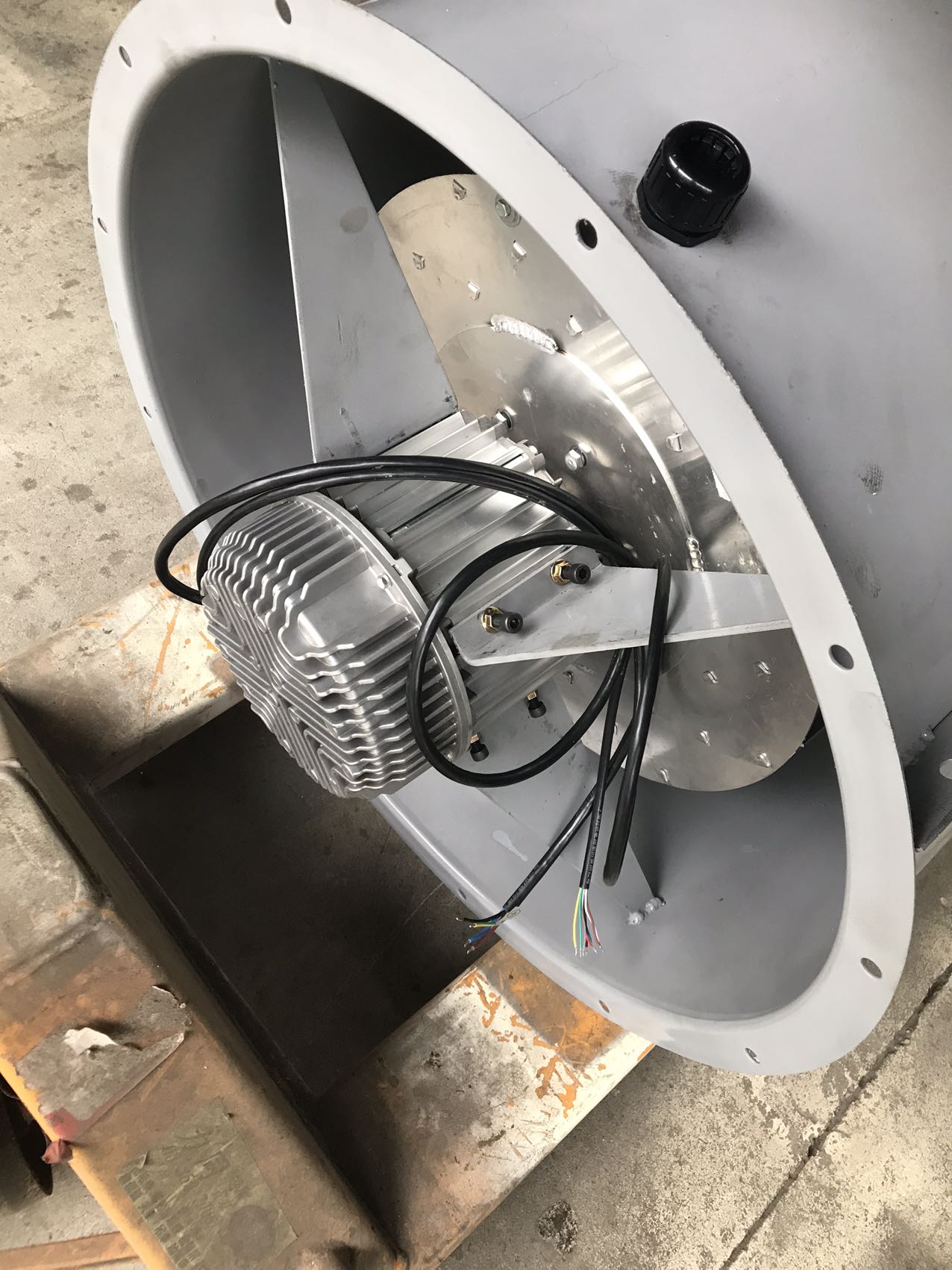
Passing IQC only guarantees good parts. In-Process Quality Control (IPQC) ensures these parts form a perfect assembly. This stage monitors real-time manufacturing precision. It catches human errors and machine drifts immediately.
Stator winding validation requires aggressive testing. Technicians implement surge testing during the winding phase. This dielectric test pushes high voltage pulses through the coils. It successfully identifies invisible micro-damage in the wire insulation. Catching a tiny scratch here prevents a major motor fire later.
Rotor and impeller dynamic balancing cannot be compromised. Multi-plane dynamic balancing prevents destructive resonance. Imbalances cause severe vibrations. These vibrations destroy bearings rapidly. Factories must target strict ISO 1940 standard balance grades. Reliable suppliers consistently achieve G6.3 or even tighter G2.5 specifications using computerized balancing machines.
Environmental protection relies on expert PCB potting. The factory must ensure uniform application of conformal coating. Skilled operators pour protective resin over the sensitive electronics. This critical step protects internal circuits from moisture, dust, and continuous vibration. It helps the unit achieve necessary IP54 to IP68 environmental protection ratings.
Finally, workers must monitor strict assembly tolerances. They verify air gap concentricity between the spinning rotor and the stationary stator. A perfectly uniform gap ensures maximum magnetic efficiency. It fundamentally prevents physical friction. Friction creates heat and noise, both of which degrade motor performance instantly.
The Final Quality Control (FQC) stage proves the engineering concept. It validates actual performance against published datasheets. Rigorous FQC separates reliable industrial equipment from commercial-grade toys.
Burn-in and aging tests eliminate early-stage electronic mortality. Facilities run 100% of finished units in high-temperature aging rooms. Temperatures typically range from 40°C to 60°C. Units run continuously for a minimum cycle. This cycle usually lasts between 4 and 24 hours. Weak electronics fail during this phase, not in your data center.
Aerodynamic testing validates airflow claims. Quality engineers conduct random batch testing inside a calibrated wind tunnel. They strictly follow AMCA standards. This testing verifies the actual airflow (CFM). It ensures the static pressure precisely matches the published P-Q performance curves. You get the exact cooling power you paid for.
Electrical safety and acoustic comfort demand rigorous verification. Hi-Pot (High Potential) testing checks insulation integrity. It guarantees the motor chassis will not electrocute operators. Alongside safety, engineers utilize anechoic chambers. They measure precise noise levels (dBA). Specialized microphones easily detect abnormal motor harmonics indicating internal mechanical friction.
EMC/EMI compliance protects your broader system network. The onboard microprocessors generate high-frequency signals. Testing verifies the controller does not emit excessive electromagnetic interference. It also proves the motor remains completely immune to dirty power and unexpected grid fluctuations.
The table below summarizes the critical testing metrics applied during the final inspection phase.
Testing Category | Standard / Metric | Primary Objective |
|---|---|---|
Burn-In Aging | 40°C to 60°C for 4-24 hours | Trigger early electronic component failures before shipping. |
Aerodynamic | AMCA Standard Wind Tunnel | Validate actual CFM and static pressure against P-Q curves. |
Electrical Safety | Hi-Pot (High Potential) Voltage | Ensure insulation integrity and prevent electrical leakage. |
Acoustic | Anechoic Chamber (dBA) | Measure sound pressure and detect abnormal motor harmonics. |
Electromagnetic | EMC/EMI Immunity Standards | Prevent grid interference and ensure signal stability. |
A pristine factory floor means nothing without documented systems. You must look beyond the basic ISO 9001:2015 certificate hanging in the lobby. You need to verify its active application across the facility. Look for clear Standard Operating Procedures (SOPs) posted prominently at every single workstation. Check the testing equipment carefully. You should see updated, visible calibration tags on every multimeter and balancing machine.
End-to-end traceability defines a world-class operation. Top manufacturers utilize sophisticated barcode or QR code systems directly on the production line. A quick scan links a finished unit back to its specific raw material batch. It records the exact assembly date. It logs the individual testing operator. This data matters immensely during troubleshooting.
Global certifications prove design maturity. Do not simply trust self-declared specifications. Demand verification of regional and safety compliance marks. You should look for UL and CE stamps indicating strict electrical safety. Ensure RoHS compliance for hazardous material restrictions. Verify ErP Directive compliance to guarantee high energy efficiency.
Procurement teams must recognize warning signs early. You must actively look for operational red flags before signing purchase orders. Certain behaviors indicate a lack of process maturity.
First, remain highly skeptical of the "zero defects" myth. No mass-production facility runs perfectly forever. If a supplier claims a 0% failure rate, they are hiding data. Instead, ask for their Corrective and Preventive Action (CAPA) process. Request a sample 8D report. You want to see exactly how they handle anomalies, analyze root causes, and implement permanent structural fixes.
Second, watch out for a lack of in-house testing equipment. A manufacturer outsourcing all their aerodynamic or environmental testing presents a huge risk. They lack the immediate R&D feedback loop. Continuous improvement requires daily testing access. If they cannot test a new impeller design immediately, their product development stalls.
Take clear next-step actions to protect your supply chain. Request a highly detailed QC flow chart before your first meeting. Ask for real sample testing reports. Demand to see actual burn-in logs and dynamic balance data sheets. Finally, schedule a comprehensive virtual or on-site factory audit. Focus your audit heavily on their active IPQC stations.
High-performance cooling systems require pristine manufacturing environments where mechanical precision and electronic stability are aggressively monitored.
Robust Incoming Quality Control prevents sub-par materials from infecting the assembly line.
Dynamic balancing and surge testing during production prevent catastrophic field failures.
End-to-end traceability ensures rapid root-cause analysis when unexpected anomalies occur.
The cheapest unit price often hides dangerous shortcuts. Low-cost suppliers frequently skip mandatory burn-in testing and precise dynamic balancing. These shortcuts cost you significantly later in system downtime. Choose a strategic partner whose internal QC infrastructure acts as your absolute first line of defense against disastrous field failures. Always request hard data, audit their processes, and demand uncompromising transparency.
A: Industry standards typically dictate running units for 4 to 24 hours at elevated temperatures (40°C to 60°C). This rigorous process aggressively stresses the internal electronics. It effectively catches early mortality failures in capacitors and microprocessors before shipment. However, highly critical medical or military applications often demand much longer, customized testing cycles.
A: Technicians use highly sensitive, computerized balancing machines. They spin the impeller to measure vibration across multiple planes. The machine calculates the exact location of mass imbalance. Operators then add small balancing clips or mill away tiny amounts of material. They repeat this process until the unit meets specific ISO 1940 vibration standards, like G6.3.
A: Traceability acts as your ultimate safety net. If a premature field failure occurs, lot traceability uses barcode data to trace the specific unit back to its exact raw material batch and assembly date. This allows you and the supplier to instantly isolate the faulty batch, limiting your liability and minimizing the scope of any potential recall.


