


Views: 0 Author: Site Editor Publish Time: 2026-07-16 Origin: Site


Electronic enclosures keep shrinking rapidly. Component density continuously rises across all industrial sectors. Engineering teams face a growing, complex challenge daily. Thermal management systems must deliver significantly higher performance. They must achieve this cooling within increasingly tighter physical constraints. Standard AC fans often fail completely here. Basic axial designs simply cannot overcome the high system impedance found inside modern compact devices. Modern electronics naturally resist smooth airflow. This severe resistance starves standard cooling methods quickly.
Enter EC centrifugal fans. They provide the definitive engineering solution for high-static-pressure applications. They combine a traditional blower's spatial efficiency smoothly. They pair it directly alongside an intelligent motor's operational excellence. You will learn exactly why these advanced fans dominate modern enclosure designs. We will explore their aerodynamic advantages thoroughly. We will also break down mechanical integration risks. You will understand how to specify them correctly for your next compact hardware project.
We must first define system impedance clearly. Compact spaces pack massive heat loads into tiny footprints. Think about outdoor telecom cabinets. Look at advanced medical imaging equipment. Consider densely populated server racks. Engineers cram more processing power into smaller boxes continuously. This reduces internal air volume drastically. It creates complex, narrow pathways for cooling air to travel. We call this airflow resistance "system impedance." Overcoming this impedance prevents catastrophic hardware failure. Trapped heat destroys sensitive microprocessors quickly. It degrades critical power supply components.
Why do standard cooling options fail these criteria? Axial fans push air in a straight, linear path. They work wonderfully in wide, open spaces. However, they stall easily against high backpressure. Tight HEPA filters block their airflow directly. Dense aluminum heat sinks restrict their movement. Sharp 90-degree duct turns kill their aerodynamic momentum completely. When internal impedance rises, axial fans lose efficiency rapidly. They spin uselessly while failing to cool the critical system components.
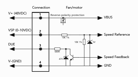
Let us break down the Electronically Commutated (EC) advantage. EC motors merge AC and DC technologies intelligently. They use permanent magnets inside the rotor assembly. Built-in circuit boards control the stator magnetic fields dynamically. This alters the centrifugal performance curve dramatically. EC motors maintain continuous electrical efficiency across varying rotational speeds. AC motors suffer sharp efficiency drop-offs when engineers slow them down. EC technology keeps torque exceptionally high. It keeps internal motor heat remarkably low.
Integrated electronics provide predictive and highly responsive cooling. Standard legacy fans run continuously at full speed. EC fans adjust their speed dynamically. They read voltage signals directly from thermal sensors. They ramp up only when temperatures rise dangerously. This smart regulation reduces unnecessary acoustic noise significantly. It lowers electrical power draw heavily during low-load periods. Your system uses the exact energy amounts needed, avoiding wasteful overcooling.
We base these efficiency claims on firm regulatory reality. They are not simple marketing fluff. Consider the European ErP (Energy-Related Products) directive. This strict legal standard mandates high minimum efficiency grades for industrial fans. Quality EC fans exceed ErP benchmarks easily. They achieve up to 90% electrical efficiency. Standard AC fans often hover around 45% efficiency. The mathematical advantage remains clear, verifiable, and crucial for modern engineering compliance.
Impeller shape dictates all aerodynamic performance. Engineers choose between three main blade designs when specifying cooling solutions. Forward-curved impellers move high air volumes at lower speeds. They suit quieter, low-pressure indoor appliances. Backward-curved impellers handle the highest static pressures available. They resist stalling under extreme system impedance. Radial impellers feature straight, paddle-like blades. They excel in harsh, particle-heavy exhaust applications. Backward-curved designs dominate modern electronics cooling due to their pressure capabilities.
| Impeller Type | Aerodynamic Characteristic | Primary Engineering Use Case |
|---|---|---|
| Forward-Curved | High volume, lower speed, lower pressure capability | Quiet indoor appliances, light ventilation |
| Backward-Curved | High static pressure, high aerodynamic efficiency | Dense server racks, high-impedance telecom cabinets |
| Radial Blade | Self-cleaning, moderate pressure capability | Industrial particle exhaust, harsh material handling |
A compact centrifugal fan functions uniquely as a blower unit. It pulls air inward along the central rotational axis. It then accelerates the air outward radially. The volute housing collects this air and exhausts it at a sharp 90-degree angle. This mechanism solves challenging mechanical packaging layouts brilliantly. Engineers can mount the fan directly into tight chassis corners. It forces air exactly where needed. It maximizes spatial economy flawlessly inside restricted enclosures.
Component lifespan improves drastically using these fans. Older brushed DC motors rely on physical carbon brushes. These brushes create constant mechanical friction. They wear out inevitably over time. They generate harmful carbon dust inside clean environments. EC technology eliminates these physical brushes completely. It relies entirely on shifting magnetic fields for continuous rotation. This lack of friction lowers operating temperatures immensely. It drastically improves the Mean Time Between Failures (MTBF). High-quality EC cooling units routinely outlast the expensive hardware they protect.
Standardizing system voltage streamlines the engineering process heavily. It simplifies overall power supply design. The 48VDC centrifugal fan represents the current global industry standard. Telecom infrastructure relies heavily on 48VDC power buses. Modern IT data centers use it extensively. Battery-powered applications prefer it for safety and efficiency. A 48V supply allows engineers to use thinner wiring. It requires lower electrical current draw for equivalent mechanical power output. This reduces dangerous resistive heat loss inside the wiring harness.
You must balance required CFM (Cubic Feet per Minute) carefully. Match it strictly against your calculated static pressure requirements. Then, evaluate your final acoustic limits. Noise-sensitive environments demand strict audio control. Medical patient wards cannot tolerate loud whirring frequencies. Office server closets must remain sonically unobtrusive. A larger impeller spinning slower reduces audible noise. A smaller impeller spinning faster increases pitch and volume. Choose your physical dimensions strategically to optimize acoustics.
Environmental conditions dictate your exact Ingress Protection (IP) rating selection. IP54 ratings protect internal electronics against everyday dust. They block light water splashes perfectly. IP68 ratings handle incredibly harsh industrial settings. They survive complete continuous water submersion. Select properly sealed electronics when deploying systems outdoors. Unprotected control boards fail quickly in salty, humid, or dusty environments.
Integrated motor electronics generate invisible electromagnetic noise. We call this Electromagnetic Interference (EMI). This noise threatens nearby sensitive microprocessors. Unchecked EMI corrupts digital data signals rapidly. It disrupts vital medical sensor readings. Engineers must address this specific integration risk early during prototyping. Advise your layout team on proper shielding techniques. Follow EMC (Electromagnetic Compatibility) compliance requirements strictly. Keep motor control cables routed far away from sensitive communication lines.
| Integration Risk | Primary Root Cause | Recommended Mitigation Strategy |
|---|---|---|
| EMI / EMC Disruption | Switching frequencies in motor commutation electronics | Use shielded cables, ferrite beads, and grounded metal chassis enclosures. |
| Acoustic Resonance | Rigid metal-to-metal mounting transmitting vibrations | Install elastomeric isolation grommets or specialized rubber dampeners. |
| Aerodynamic Stalling | Mismatched performance and system impedance curves | Map theoretical fan CFM against actual system pressure before finalizing selection. |
Mounting centrifugal blowers involves strict structural realities. Improper mounting causes severe acoustic problems inside a compact chassis. Hard-mounting transmits raw motor vibrations directly into the metal frame. This vibration amplifies quickly across flat panels. It creates loud, annoying acoustic resonance. We highly recommend modern mechanical isolation techniques. Use specialized rubber mounts. Install high-density dampening gaskets. Decouple the fan body from the main structural housing entirely.
Warn your team strongly against over-specifying a fan unit. Bigger is absolutely not always better. You must map the fan's precise performance curve accurately. Overlay it directly onto the actual calculated system impedance curve. The exact intersection represents your real-world operating point. Ignoring this vital step leads to aerodynamic surging. It causes sudden, unpredictable stalling. The fan might consume maximum electrical power while moving virtually zero air.
Combining intelligent EC motors with centrifugal aerodynamics solves critical packaging challenges immediately. It overcomes high internal system resistance smoothly. It satisfies strict physical space budgets simultaneously. Engineers gain unprecedented control over their thermal environments.
Always prioritize your static pressure capability first during selection. Ensure voltage compatibility early in the initial design phase. A standardized 48V bus simplifies integration immensely across large platforms. Define your exact speed control requirements clearly to maximize efficiency gains.
Review specific technical data sheets for accurate airflow curves today. Download detailed 3D CAD models for immediate spatial testing inside your enclosure layout. Request a physical blower sample for thorough thermal chamber validation. Test it rigorously against your actual measured system impedance.
A: Both units may use DC power. However, EC fans feature built-in commutation electronics. This enables intelligent, stepless speed control. It also manages AC-to-DC conversion internally if required. They offer significantly higher efficiency. They provide much longer lifespans than traditional brushed DC blowers.
A: A 48V supply allows for thinner wiring layouts. It demands lower current draw for the exact same power output. This reduces resistive heat loss inside cables. Furthermore, 48V remains the standard bus voltage for global telecom operations. It dominates modern IT infrastructure designs entirely.
A: Yes. Manufacturers design many EC fans as exact drop-in replacements for older legacy AC models. They accept standard AC input directly. They internally convert this to DC power. This drives the high-efficiency motor seamlessly. It provides an immediate energy upgrade without redesigning the chassis.
A: You can control them using multiple standardized methods. They typically accept a simple PWM (Pulse Width Modulation) signal. They also respond predictably to a 0-10V analog input. Advanced models offer digital MODBUS communication. This allows them to interface seamlessly with environmental sensors and centralized system controllers.
