


Views: 0 Author: Site Editor Publish Time: 2026-07-22 Origin: Site


Upgrading or designing modern ventilation systems requires balancing strict energy efficiency mandates with reliable airflow performance. You face increasing pressure to meet rigorous building codes while maintaining optimal air quality. Legacy AC and standard DC motors dominate older infrastructure. However, Electronically Commutated (EC) technology has quickly become the baseline for performance-critical applications today. Selecting the exact specification goes far beyond basic airflow matching. It requires a systematic evaluation of control integration, acoustic profiles, and environmental resilience to ensure reliable operation.
We will guide you through this entire selection process step by step. You will learn how to match aerodynamic parameters to your specific system requirements. We will also explore hardware resilience, variable speed control integration, and vendor evaluation methodologies. By the end, you will know exactly how to specify the optimal unit for your next project.
Before selecting a motor type, you must confirm your basic aerodynamic needs. Projects requiring high-volume, low-pressure linear airflow perfectly match the core use case for a ventilation axial fan. Centrifugal blowers handle high-resistance ductwork better. Axial models excel at moving massive amounts of air across open spaces, heat exchangers, or short duct runs.
Once you confirm the axial requirement, you must evaluate motor technologies. Traditional AC motors operate at fixed speeds based on grid frequency. They waste significant energy when systems require partial loads. DC motors offer variable speed control. They require external rectifiers and suffer from mechanical brush wear. EC motors solve both problems. They combine AC power input with internal DC voltage conversion. Electronic commutation replaces physical brushes entirely. This design delivers intelligent speed control directly out of the box.
Upgrading to a EC axial fan heavily impacts long-term operations. They demand a higher upfront capital expenditure. However, they deliver immense operational savings. They consume significantly less electricity over their operational lifespan. They also require practically zero motor maintenance because they lack mechanical brushes.
Scalability and regulatory compliance drive this adoption further. EC technology inherently supports modern HVAC energy standards. Regulations like the European ErP directive mandate strict efficiency minimums. Traditional AC motors struggle to meet these targets. EC units easily surpass them. Furthermore, they integrate seamlessly into smart-building systems. You can scale your ventilation network easily as facility demands grow.
Sizing your equipment incorrectly leads to catastrophic system failures. You cannot simply read the highest number on a manufacturer datasheet. You must align aerodynamic parameters with your physical installation.
You must understand the relationship between airflow and static pressure. Every component in your air path creates resistance. Ductwork, HEPA filters, dampers, and louvers impede air movement. This total resistance creates your system impedance curve.
To find the correct operating point, plot your required airflow (CFM or CMH) against your calculated system impedance. Never size your equipment based solely on "free air" delivery metrics. Free-air ratings assume zero resistance. If you install a fan based on this metric, it will choke immediately upon facing real-world filters or grilles. Always demand comprehensive performance curves from your manufacturer. Ensure your required duty point falls within the most efficient zone of the provided curve.
Noise levels dictate usability in many environments. You must evaluate dBA requirements based on the specific installation site. Commercial offices and hospitals require extremely quiet operation. Industrial warehouses tolerate higher decibel levels.
Motor type drastically impacts acoustic performance. When you reduce the speed of a traditional AC motor using a Variable Frequency Drive (VFD), it often generates a loud, irritating magnetic "hum." EC motors eliminate this issue completely. Their internal electronics manage commutation smoothly. They remain virtually silent even when running at 10% capacity.
Blade design and housing geometry play massive roles in aerodynamic efficiency. Engineers optimize these physical traits to reduce turbulence and maximize thrust.
Consider the following common blade designs:
Housing design matters equally. A well-designed bell-mouth housing smoothly guides air into the impeller. This prevents vortex shedding and maximizes volumetric efficiency.
| Parameter | Standard AC Setup | Modern EC Setup | Primary Benefit |
|---|---|---|---|
| Speed Control | External VFD Required | Integrated Electronics | Saves installation space |
| Acoustics (Low Speed) | High magnetic hum | Virtually silent | Improves occupant comfort |
| Operating Range | Narrow peak efficiency | Broad high-efficiency zone | Adapts to filter loading |
| Power Input | Strict AC frequency dependence | Wide voltage tolerance | Resists grid fluctuations |
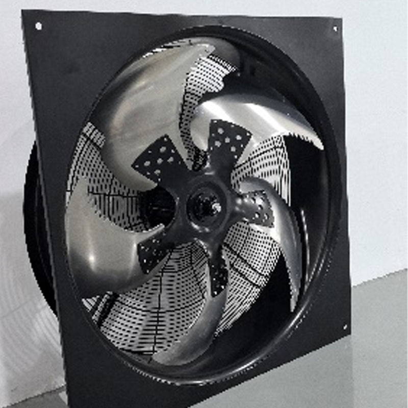
Ventilation equipment rarely operates in pristine conditions. You must evaluate the deployment environment carefully. Hardware resilience dictates long-term reliability.
Categorize your deployment accurately before ordering. Commercial HVAC systems operate in relatively benign conditions. They handle conditioned air and moderate humidity. Data center cooling systems face constant, high-velocity thermal loads. They require exceptional continuous-duty reliability. Heavy industrial ventilation faces the worst conditions. These environments subject equipment to corrosive gases, heavy particulates, and extreme temperature swings.
Moisture and dust destroy sensitive electronics. You must specify appropriate IP ratings for your deployment zone. The ingress protection rating is non-negotiable for external or harsh installations.
Impeller and housing materials dictate physical longevity. Plastic and composite impellers resist standard moisture well. They keep total unit weight low. Aluminum and steel impellers handle higher temperatures and physical stress. They suit heavy-duty industrial applications.
You must address hazardous environments specifically. Chemical plants or oil refineries require corrosion-resistant coatings. Explosive (ATEX) environments mandate spark-resistant construction. These specialized units use specialized alloys to prevent accidental ignition during operation.
Excellent hardware means nothing without proper integration. EC technology provides advanced control capabilities. You must understand how to deploy them correctly to avoid operational headaches.
These motors natively support several communication protocols. You can choose the best fit for your building management system (BMS).
Improper wiring often ruins sophisticated deployments. You must address electromagnetic interference (EMI) immediately. The internal electronics generate high-frequency switching noise. You must use shielded control cables. You must ground all equipment strictly according to manufacturer guidelines. Ignoring grounding best practices will corrupt your Modbus signals and cause erratic speed fluctuations.
Structural resonance presents another major risk. Every building structure has a natural resonant frequency. If your motor runs exactly at this frequency, it will cause violent vibrations. These vibrations destroy mountings and ductwork. You must identify these resonant frequencies during commissioning. Most modern EC firmware allows you to program "skip frequencies." The motor will automatically accelerate past these dangerous RPM zones.
Replacing legacy AC fans requires mechanical and electrical adjustments. Mechanically, you might need adapter plates. The bolt patterns on modern housings occasionally differ from decades-old legacy units.
Electrically, you must adjust your supply logic. You can no longer use existing VFDs. You must bypass them entirely. EC models connect directly to stable AC mains power. You then pull separate, low-voltage wiring to handle the speed control signals. Mixing high-voltage mains and low-voltage control lines in the same unshielded conduit will cause severe interference.
The market contains hundreds of component suppliers. Not all deliver consistent quality. You must evaluate manufacturers systematically before committing to a large purchase.
Do not accept internal testing documents at face value. Demand universally recognized certifications. Look for UL, CE, and RoHS marks to ensure basic electrical safety and material compliance.
For aerodynamic performance, demand independent verification. Certifications from the Air Movement and Control Association (AMCA) prove reliability. AMCA-certified data guarantees the unit actually moves the air the datasheet claims. ISO standard compliance further indicates rigorous manufacturing consistency.
Every project has unique quirks. Assess the vendor’s ability to accommodate them. A reliable manufacturer will provide customized wiring harnesses to speed up your installation. They can flash specific firmware configurations before shipping. They should also offer specialized mounting hardware tailored to your specific application environment.
Hardware delays derail construction timelines. Evaluate the vendor's supply chain stability. Ask for realistic lead times during peak seasons. Review their warranty terms carefully. Ensure they offer multi-year coverage on electronic components.
Finally, confirm the availability of localized engineering support. When deployment anomalies occur, you need experts available in your time zone. A responsive technical support team prevents minor integration issues from becoming major project roadblocks.
Specifying the correct equipment is a strategic decision. You must carefully balance aerodynamic performance, motor efficiency, and advanced control capabilities. Moving away from legacy AC systems towards modern electronically commutated alternatives future-proofs your facility. It ensures compliance with modern energy directives while providing granular environmental control.
Your next step requires gathering accurate site data. Compile your system impedance calculations carefully. Document your environmental constraints, including temperature ranges and required IP ratings. Take this data to a qualified engineering team. Request detailed performance curves and 3D CAD models. This proactive approach guarantees a smooth installation and years of reliable operation.
A: Yes. Mechanically, they often serve as precise drop-in replacements. However, the electrical wiring differs significantly. They connect directly to AC mains power. They require completely separate low-voltage control wiring to manage their variable speed functions.
A: First, calculate the total volume of your physical space. Multiply this volume by the required Air Changes per Hour (ACH) dictated by your specific industry standards. Finally, divide that number by 60. This gives you the required CFM baseline.
A: This usually happens due to higher-than-expected system static pressure. Dirty filters, complex ducting, or restrictive louvers choke the airflow. You must always evaluate the performance curve against your actual system impedance, not free-air metrics.
A: No. These motors feature integrated electronics that manage speed control natively. This built-in capability eliminates both the cost and the physical space required to install external VFDs.
